Introduction
Here are very popular schematics:
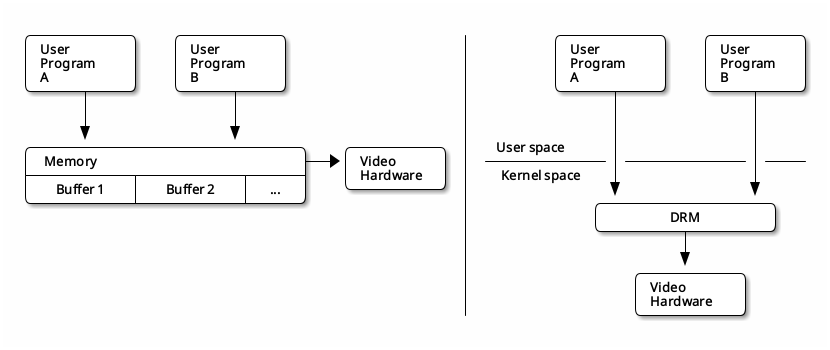
It shows in a simple and clear way the Linux Kernel Graphics Stack structure before and after September 2009 when the DRM system was introduced. From then, many drivers were rewritten to match the new environment and use the full potential of newly added functionalities.
But plenty of drivers still need to be ported for DRM system or have some key
functionalities missing. This post describes a story of implementing a feature
called bridge chaining.
DRM bridges chaining implementation process
One of the key features of the DRM system is the possibility to integrate
several bridges into one video chain to convert from one video format to
another. This feature is described in Linux Kernel
documentation as still in-flux and not really fully sorted out yet, so, problems with implementation were expected. But nobody said it is
going to be easy!
Structure
Hardware used:
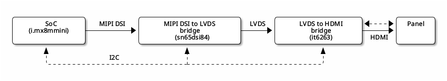
i.mx8mminiSoC;sn65dsi84MIPI DSI to LVDS bridge;it6263LVDS to HDMI bridge.- HDMI panel.
The plan was to generate DSI video signal from SoC, convert it to LVDS, then convert it to HDMI, and, finally, feed the HDMI panel. The entire operation was being controlled by the system via the I2C interface to which all bridges were connected. So, the hardware structure is following:
Software used:
- GNU/Linux v5.15;
- Weston (the reference implementation of a Wayland server) v10.0.1.
Responsibilities for generating graphics among software were split into two parts; both use DRM system:
- kernel space: responsible for generating graphics during boot (logo, console, etc.), is directly driven by Linux Kernel;
- userspace: responsible for generating graphics after boot, is driven by several userspace clients and graphic server (Weston in this case).
The switch is performed when Weston is being loaded by systemd.
Implementation process
Hardware setup and configuration
Hardware setup was rather easy:
- Connect all the needed wires;
- Do not miss any data and clock I2C wires, otherwise it could be difficult to debug later.
So as devicetree configuration:
-
Enable needed subsystems (LCDIF, MIPI DSI, etc.);
-
Register bridges under chosen I2C buses and configure them, here is for example
it6263andsn65dsi84configurations (for details, refer toit6263.cdevicetree documentation andti-sn65dsi83.cdevicetree documentation):1 2 3 4 5 6 7 8 9 10 11 12 13 14 15 16 17 18 19 20 21 22 23 24 25 26 27 28 29 30 31 32 33 34 35 36 37 38 39 40 41 42 43 44 45 46 47 48 49 50&i2c3 { lvds-to-hdmi-bridge@4c { compatible = "ite,it6263"; reg = <0x4c>; pinctrl-names = "default"; pinctrl-0 = <&pinctrl_it6263_en>; reset-gpios = <&gpio5 2 GPIO_ACTIVE_LOW>; status = "okay"; port { it6263_in: endpoint { remote-endpoint = <&lvds_out>; }; }; }; mipi_to_lvds: sn65dsi84@2c { compatible = "ti,sn65dsi83"; reg = <0x2c>; enable-gpios = <&gpio1 6 GPIO_ACTIVE_HIGH>; interrupts-extended = <&gpio1 5 GPIO_ACTIVE_HIGH>; clocks = <&mipi_dsi 0>, <&clk IMX8MM_CLK_LCDIF_PIXEL>; clock-names = "mipi_clk", "pixel_clock"; display = <&display_subsystem>; pinctrl-names = "default"; pinctrl-0 = <&pinctrl_i2c1_sn65dsi84>; sync-delay = <512>; dsi-lanes = <4>; status = "okay"; lvds_ports: ports { #address-cells = <1>; #size-cells = <0>; port@0 { reg = <0>; lvds_in: endpoint { remote-endpoint = <&mipi_out>; data-lanes = <1 2 3 4>; }; }; port@2 { reg = <2>; lvds_out: endpoint { remote-endpoint = <&it6263_in>; attach-bridge; }; }; }; -
Configure power controllers (for details, refer to the appropriate devicetree documentation):
1 2 3 4 5 6 7 8 9 10 11 12 13 14 15 16 17 18 19 20 21 22®ulators { reg_lvds_pwr: lvds_pwr { compatible = "regulator-fixed"; pinctrl-names = "default"; regulator-name = "lvds_pwr_en"; pinctrl-0 = <&pinctrl_lcd_3v3_enable>; gpio = <&gpio4 29 GPIO_ACTIVE_HIGH>; enable-active-high; regulator-boot-on; regulator-always-on; }; reg_5v_bl: 5v_bl { compatible = "regulator-fixed"; pinctrl-names = "default"; regulator-name = "5v_bl_en"; pinctrl-0 = <&pinctrl_lcd_5v_enable>; gpio = <&gpio5 5 GPIO_ACTIVE_HIGH>; enable-active-high; regulator-boot-on; regulator-always-on; }; }; -
Add
i.mxinput-output multiplexers (for details, refer to the appropriate devicetree documentation):1 2 3 4 5 6 7 8 9 10 11 12 13 14 15 16 17 18 19 20 21 22 23&iomuxc { pinctrl_lcd_3v3_enable: lcd_3v3_en { fsl,pins = < MX8MM_IOMUXC_SAI3_RXC_GPIO4_IO29 0x19 >; }; pinctrl_lcd_5v_enable: lcd_5v_en { fsl,pins = < MX8MM_IOMUXC_SPDIF_EXT_CLK_GPIO5_IO5 0x19 >; }; pinctrl_it6263_en: it6263_en { fsl,pins = < MX8MM_IOMUXC_SAI3_MCLK_GPIO5_IO2 0x19 >; }; pinctrl_i2c1_sn65dsi84: i2c1-sn65dsi83grp { fsl,pins = < MX8MM_IOMUXC_GPIO1_IO05_GPIO1_IO5 0x04 MX8MM_IOMUXC_GPIO1_IO06_GPIO1_IO6 0x106 >; }; };
After above changes both chips were detected on I2C buses, here is sn65dsi84
on i2c-0 under address 2c:
|
|
Drivers
Then, it was high time to add appropriate drivers to the image. In theory, after adding drivers, the entire graphic chain presented in Structure chapter above should work, with no need for additional kernel or Weston configuration. Let’s see then.
Following drivers were chosen to drive this chain:
- for
sn65dsi84: driver fromvarigit/linux-imxrepository - for
it6263: driver fromnxp-imx/linux-imxrepository
Checking whether the system recognized the drivers may be done via sysfs:
|
|
Bridge chaining
The first boot result was not very pleasurable: several errors in dmesg from
sn65dsi84 driver and no messages from it6263 driver. No video output was
noticed as well:
|
|
Ok then, all sn65dsi84 errors were fixed, it was a matter of devicetree
configuration. But still no video on the panel.
Note: the above errors and the way they were fixed are not explained because the
sn65dsi84driver fromvarigit/linxu-imxrepository, the source of these messages, will be replaced by another. This driver is presented here only to demonstrate that some drivers are not entirely compatible with the DRM system.
Several checks were done to check every part of the system separately:
- Checking
sn65dsi84with LVDS panel proved correct driver and hardware configuration by showing some video output; - Checking communication via I2C with
it6263proved correct connection (some register write/read operations were done); - Checking the HDMI panel proved correct connection and functionality by showing video output connected to another platform.
Still, there are no clues as to where the problem is.
While checking the code of the sn65dsi84 driver from the varigit/linux-imx
repository the absence of a call to drm_bridge_attach()
function in the attach function was noticed. So,
it6263 simply was not attached to the chain by sn65dsi84 as it should be.
After several experiments decision to use sn65dsi84 driver from
nxp-imx/linux-imx repository was made, here is a call to
drm_bridge_attach() from the repository:
|
|
So, after performing all operations needed to attach sn65dsi84 to the previous
bridge or encoder in the chain this call executes the next bridge’s attach
function.
After switching to another sn65dsi84 driver, both bridges were successfully
probed and recognized by the DRM system:
|
|
Note:
dmesglogs from above are provided by addingprintk()to the drivers source code.
After further analysis, the following problems were pointed out:
-
No video output on the panel during boot as well as in userspace;
-
Weston argues that one
drm_connectordoes not have CRTC assigned:1 2 3 4 5 6 7 8 9 10 11[11:44:08.403] weston 10.0.1 (...) [11:44:09.436] Output 'DSI-1' using color profile: built-in default sRGB SDR profile [11:44:09.444] Output DSI-1 (crtc 33) video modes: 1280x720@59.9 16:9, current, 74.2 MHz [11:44:09.444] Output 'DSI-1' enabled with head(s) DSI-1 [11:44:09.444] Module '/usr/lib/libgbm.so' already loaded [11:44:09.444] Output 'HDMI-A-1' using color profile: built-in default sRGB SDR profile [11:44:09.444] Output 'HDMI-A-1': No available CRTCs. [11:44:09.444] Enabling output "HDMI-A-1" failed. [11:44:09.444] Error: cannot enable output 'HDMI-A-1' without heads.
Weston issue
According to Linux Kernel DRM/KMS system documentation the KMS structure should be following:
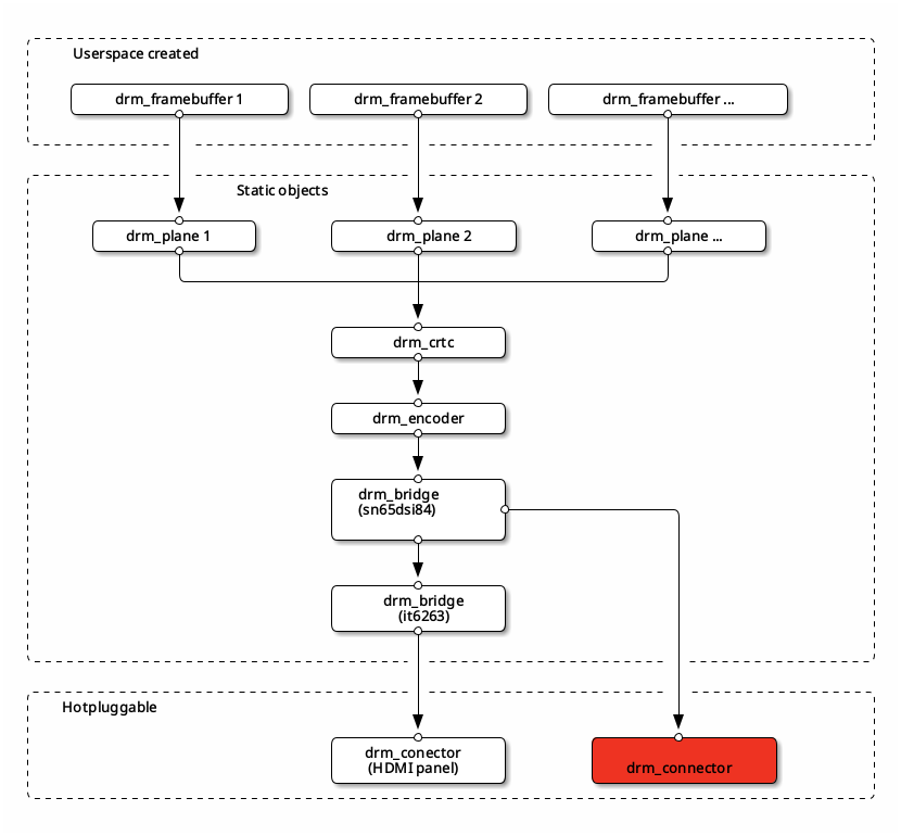
The red-marked drm_connector structure is surplus and is causing the Weston
issues.
According to comments in drm_bridge_connector.c
and to comments in drm_bridge.c file, to create
drm_connector for a chain of bridges, DRM drivers should match the following
requirements:
- Encoder or display controller drivers should:
- Create
drm_connectorstructure and initialize it by usingdrm_bridge_connector_init()function fromdrm_bridge_connector.c;
- Create
- Bridge drivers should:
- Export following functions via
drm_bridge_funcs(some of them are optional):drm_bridge_funcs.detect(),drm_bridge_funcs.get_modes(),drm_bridge_funcs.get_edid(),drm_bridge_funcs.get_edid(),drm_bridge_funcs.hpd_enable()anddrm_bridge_funcs.hpd_disable().; - Export its type and functionalities via flags
drm_bridge.typeanddrm_bridge.ops - Implement conditional connector creation or not create connectors by themselves.
- Export following functions via
To implement the above requirements the following files were modified:
sec-dsim.c(driver for MIPI DSI transmitter) - to implement the creation ofdrm_connectorstructure for the chain of bridges;ti-sn65dsi84.c- to export appropriate functions viadrm_bridge_funcsand to export type and functionalities viadrm_bridge.typeanddrm_bridge.ops;it6263.c- to export appropriate functions viadrm_bridge_funcs, implement conditional creation ofdrm_connectorstructure and to export type and functionalities viadrm_bridge.typeanddrm_bridge.ops.
Weston has not argued anymore about connectors:
|
|
But still no video output on the panel.
No video output issue
For now, the KMS infrastructure looks like this:
|
|
Quick summary:
- System correctly recognizes the chain;
- EDID is being read and interpreted;
- Connector got nine modes from EDID with one set as
preferred; - Preferred mode is set as
current; - All elements of the chain are connected to each other and have expected information attached to it;
- No video on the HDMI panel during boot as well as in userspace.
After several days in complete darkness, a light in the tunnel was found. During
one of many experiments, penguins (Linux Kernel logo) showed up during boot.
It happened after forcing the system to use a mode with a specific pixel clock
frequency. All other modes were checked to prove that the issue was hidden in
modes. To force the kernel, video command line parameter
was used; on the other hand, to force Weston, weston.ini was used.
Additionally following changes were added:
-
Commit
c35a6e6c8c59e43b5080a6c77c2866ed9e01a77bfromnxp-ixm/linux-imxrepository; -
Changed
sn65dsi84configuration fromburstvideo mode toburst with sync pulsesvideo mode:1 2 3 4 5 6 7 8 9 10 11 12 13diff --git a/drivers/gpu/drm/bridge/ti-sn65dsi83.c b/drivers/gpu/drm/bridge/ti-sn65dsi83.c index d0a5c5328eae..62058ee91b0a 100644 --- a/drivers/gpu/drm/bridge/ti-sn65dsi83.c +++ b/drivers/gpu/drm/bridge/ti-sn65dsi83.c @@ -274,7 +274,7 @@ static int sn65dsi83_attach(struct drm_bridge *bridge, dsi->lanes = ctx->dsi_lanes; dsi->format = MIPI_DSI_FMT_RGB888; - dsi->mode_flags = MIPI_DSI_MODE_VIDEO | MIPI_DSI_MODE_VIDEO_BURST; + dsi->mode_flags = MIPI_DSI_MODE_VIDEO | MIPI_DSI_MODE_VIDEO_SYNC_PULSE; ret = mipi_dsi_attach(dsi); if (ret < 0) {
And… That it, the panel shown perfect picture during boot as well as in userspace! It seems that connector had not only suitable modes for used hardware but nonsuitable as well.
DRM system has tools to filter out inappropriate modes. Every bridge driver
should specify limitations to modes in drm_bridge_funcs.mode_valid() function.
After doing so, the list of modes in the connector was limited to only two modes,
so the system had only two choices:
|
|
In such cases the Linux Kernel sets as current the mode with the bigger
resolution and frame rate. As a result, the mode with a resolution 1280x720
and a frequency of 60 Hz was chosen:
|
|
Summary
The DRM system is a great step forward compared to big all-in-one graphic servers. The idea of its abstractions presents that even such complex systems can be built and described in a straightforward way even for newbies, it still requires some attention and care from developers, though.
For those who want to dive deeper into the DRM system, I recommend the following resources:
- Latest Linux Kernel documentation
- The DRM/KMS subsystem from a newbie’s point of view, Boris Brezillon
- DRM KMS overview, wiki.st.com
- Anatomy of an Atomic KMS Driver, Laurent Pinchart
- Atomic mode setting design overview, part 1, Daniel Vetter
- Atomic mode setting design overview, part 2, Daniel Vetter
- An Overview of the Linux and Userspace Graphics Stack, Paul Kocialkowski
- Standardizing Linux DRM drivers implementations by interfacing DRM Bridge as a single API, Jagan Teki