Minnowboard Turbot remote firmware flashing with RTE (Remote Testing Environment)
Introduction
Work related to a hardware carries some restrictions which don’t occur when working only with a software. One of them is a limited number of devices. This one may cause a problem with a accessibility to the platform. The limited number of users could slow development and testing. What is more work with a hardware requires a minimal knowledge of the theory of circuits and signals to eliminate platform damage by a user. Hardware can be expensive too.
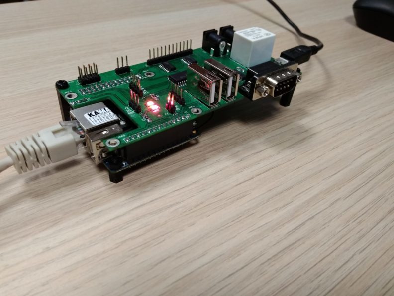
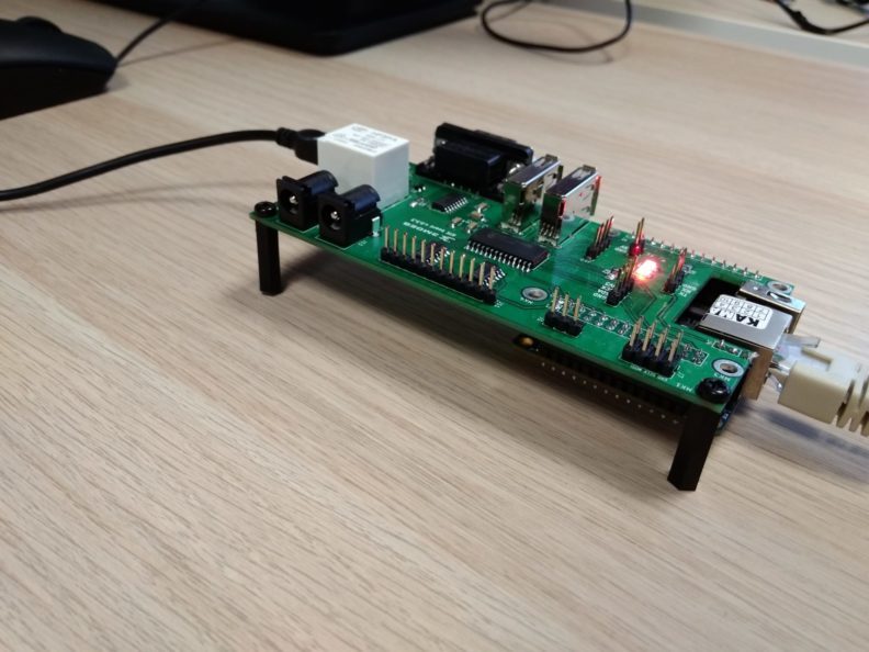
Remote Testing Environment project was made to resolve mentioned problems. The
result of work is shown below: 

That platform makes possible to work on a hardware remotely. RTE connected to the tested device can provide some more advantages like:
- Possibility to built testing system only once and place it in separated and secure place.
- Advantage described above allows to keep order and eliminate time wasting for items search and connect.
- Reduced number of hardware requirements for the user. Now he needs only a computer with a network connection and installed tools.
Selected RTE functionality:
- SPI with a header,
- I2C with a header,
- RS232,
- OC buffer outputs header,
- GPIO,
- USB,
- built-in relay with DC Jack 2.5/5.5 mm connectors to DUT power supply control.
Remote Testing Environment is open source hardware project based on the CERN license. You can download schematic files from here and use it for your own. Enjoy!
RTE + Minnowboard Turbot
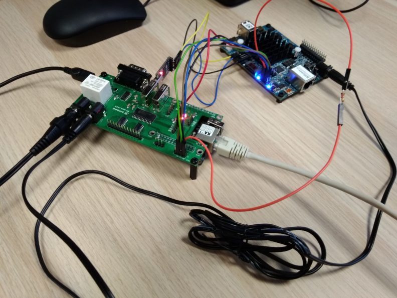
To provide remote access to the Minnowboard Turbot platform it was connected to the RTE.
Connection

- Power supply
5 V power supply for Minnowboard Turbot was connected to the RTE J12
connector. Then, DC Jack - DC Jack wire was connected to the J13 of RTE and to
the J9 of Minnowboard. That configuration allows controlling power supply
remotely.
- SPI
| Minnowboard J1 | Color | RTE |
|---|---|---|
| 1 | red | 1 (J9) |
| 2 | black | 2 (J1) |
| 3 | orange | 3 (J1) + 1.2 kΩ resistor |
| 4 | green | 4 (J1) |
| 5 | blue | 5 (J1) |
| 6 | brown | 6 (J1) |
| 7 | - | NC |
| 8 | - | NC |
- UART debug
| Minnowboard J4 | Color | UART-USB converter |
|---|---|---|
| 1 | black | GND |
| 2 | - | NC |
| 3 | - | NC |
| 4 | blue | TX |
| 5 | yellow | RX |
| 6 | - | NC |
There was one but important problem with the built system. Memory flashing was
realized correctly, but Minnowboard doesn’t boot. The source of the problem was
CS# signal. It was set to 0, so memory was always enabled, but it was not
enough. Minnowboard still doesn’t boot. So I decided to use an oscilloscope.
That analysis showed me that Minnowboard Turbot doesn’t set memory chip’s CS#
input to 0 all the time. It changes over the time. Mostly CS# is set to 0,
but periodically it’s being set to 1.
Time analysis of the CS# states seemed to be too time-consuming and trying
correct control of the CS# lines too inflexible in the event of changes. I
needed to reduce the impact of the CS# RTE output to make it a Minnowboard
Turbot took precedence in choosing the state of the CS# line. I decided to use
1.2 kΩ resistor between RTE CS# output and Minnowboard Turbot CS# input and
this was a good idea.
After resolving CS# problem, flashing procedure is very simple. It amounts to:
- Turn off the Minnowboard platform power supply.
- Flash Minnowboard ROM memory via SPI.
- Turn on Minnowboard platform power supply.
And it’s that all.
Firmware flashing
I used 2 version of firmware to test presented Remote Testing Environment:
MNW2MAX1.X64.0097.D01.1709211100.bin,
MNW2MAX1.X64.0097.D01.1709211100.bin.
Code of flashing script (flash_mw.sh):
|
|
To verify correctness of firmware flashing executed by RTE I saved UEFI Shell logs received before flashing process:
|
|
Then I saved flashing in RTE /root/ directory and executed it. Syntax is
following:
|
|
|
|
Minnowboard Turbot was turned off, flashed and later turned on. UEFI Shell prompt which I received after Minnowboard Turbot firmware flash:
|
|
As you can see, firmware flashing process carried out by RTE finished
successfully. Minnowboard Turbot boots correctly to the UEFI Shell. Firmware
version was updated. Before flashing was UEFI v2.50 after is UEFI v2.60.
Firmware flashing tests
After successfully Minnowboard Turbot firmware flashing and correctly platform
booting I decided to go one step ahead and write flashing and booting tests
using Robot Framework. RTE can be controlled using SSH and has redirected serial
port via telnet, so tests can be launched on any computer with installed
required software. The test which I wrote, copies the firmware file to RTE and
flashes Minnowboard Turbot via SPI using flashrom. Robot Framework ensures
logs what is really useful in the validation process.
Test start script syntax:
|
|
IP of RTE which I used:
|
|
The entire test launch procedure is shown below.
Create and run virtual environment for test:
|
|
Install Robot Framework in the virtual environment:
|
|
Get test files from our repository:
|
|
And launch test. Remember to give the correct directory to ROM file which you want to use:
|
|
Results
|
|
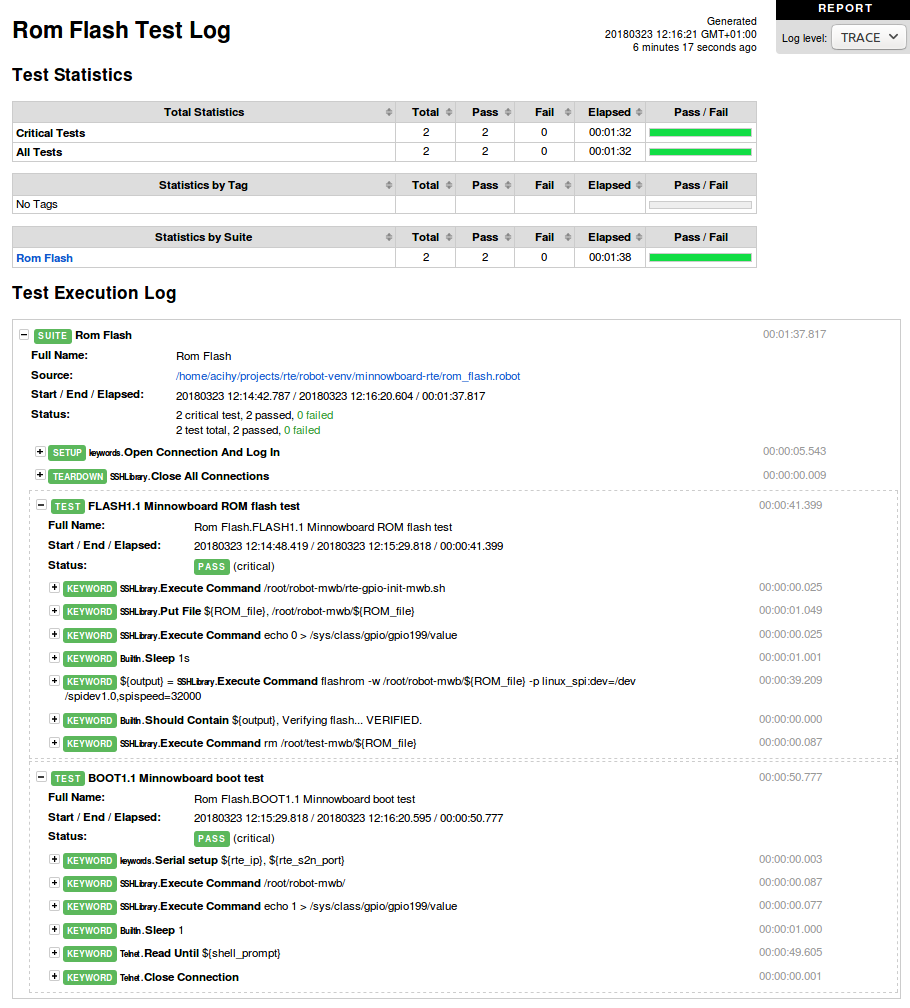
Test logs in HTML file: 
It means that Minnowboard Turbot firmware flashing process ran correctly and then platform booted to the UEFI Shell. Test finished with a success, everything works.
Other platforms
Minnowboard Turbot is not the only platform which we connected with RTE. We built a remote testing system with PC Engines APU platforms too. That solution resolved a problem with constantly moving platforms. Before RTE usage, every activity related to PC Engines APUs was linked with platform and power supply searching, connecting wires, finding a place on a table for a system under test. After we connected PC Engines platforms with RTE there is not necessary to do that anymore. We placed every RTE + PC Engines APU system in our laboratory. Now we can develop firmware and test platforms without constantly leaving the computer. Trust me, it’s very comfortable.
Conclusion
Remote work with hardware could be just as comfortable as work with only software without losing most of the functionality. All you have to do is to build earlier a system for a platform which you want to test. Our RTE proved that it is possible. I hope that the solution presented in this article convinced you too.
This solution allows to work remotely but it isn’t the only advantage. The next one is to automate tasks performed by humans. Tedious and repetitive activities can be done by machine e.g. RTE. Automation can save employees time. Every saved time is valuable and can help to increase profits.
The number of platforms connected to RTE in our laboratory still increases. I am convinced that this will not change in the near future. I will write it again, it’s comfortable.
