STM32 MCUs come with various peripherals, one of them is SPI (Serial Peripheral
Interface) which is a simple serial bus interface commonly used for
short-distance communication between various devices. SPI is one of the
interfaces used by TPM chips for communication with PC motherboard. SPI uses 4
lines for communication: MOSI, MISO, SCK, SS, which are described down below.
The device must implement the TPM protocol to work as a TPM module. TPM protocol
works by transmitting variable-length frames over SPI. The 4-byte TPM header
contains fields describing the length of the data payload, the address of the
target TPM register, and the transfer direction (read or write). TPM protocol
has its own means of handling flow control (as there isn’t a standard flow
control mechanism on SPI) and for doing bus aborts.
TPM must be able to operate at frequencies from 10 MHz to 24 MHz to comply with
the TCG PTP specification
(see section 7.4.1 and TwPM Documentation).
Getting SPI right on such high frequencies is a significant challenge,
especially when operating as a slave.TPM-specific features complicate things
further. Some platforms require TPMs to support higher frequencies. PTP
specification encourages support for the 33-66 MHz range in addition to the
required range of 10-24 MHz, and future versions of the specification may
mandate higher frequencies, so the platform should be capable of handling them.
Limitations of STM32L476
STM32L476 has SPI capable of frequencies up to a (theoretical) limit of 40 MHz,
which is half of the maximum clock that can be provided to Cortex-M and AHB/APB
buses. SPI capabilities are described in the STM32 Programming Manual
(RM0351)
section 42.2.
Another limiting factor is maximum GPIO speed, which depends on operating
conditions such as the voltage provided to the MCU, ambient temperature, and
parameters of cables used to connect the master and slave. GPIO limitations are
described in the STM32L476RG
datasheet in section 6.4. Table 72 describes the maximum frequency of GPIO
outputs.
More problematic may be DMA limitations. The hard limit of DMA transfer speed
would be 80 Mbits/s as 80 MHz is the maximum frequency that can be provided to
the AHB bus and the MCU. The actual transfer speed may be lower due to AHB and
APB protocol overhead, bus contention, etc. Unfortunately, the datasheet does
not provide information about DMA transfer limitations.
Last but not least, the performance of the firmware itself is significant.
Achieving target frequency may require extensive optimizations.
Creating SPI slave on Zephyr
Zephyr is our platform of choice primarily due to its portability (we will
target non-STM32 platforms too). I will briefly describe the outcome of my early
tests done on Zephyr and why it was terrible.
The application just transmits a static sequence of bytes:
 1
 2
 3
 4
 5
 6
 7
 8
 9
10
11
12
13
14
15
16
17
18
19
20
21
22
23
24
25
26
27
28
29
30
31
32
33
34
35
36
|
const struct device *spi_dev = NULL;
struct spi_config spi_cfg = {
    .frequency = 25000000,
    .operation = SPI_WORD_SET(8) | SPI_TRANSFER_MSB | SPI_OP_MODE_SLAVE,
};

const uint8_t testdata[32] = {
    0x3d, 0x7f, 0x85, 0xc3, 0x86, 0x2f, 0x14, 0x2a, 0xa2, 0x67, 0x1d, 0xd7, 0xfa, 0xa8, 0x3a, 0x42,
    0xf8, 0x12, 0xd2, 0xa1, 0x04, 0xcc, 0xe2, 0xc6, 0x78, 0x73, 0x09, 0xe6, 0xd8, 0xc5, 0x0e, 0xba,
};

void main(void) {
    spi_dev = device_get_binding(DEVICE_DT_NAME(DT_NODELABEL(spi2)));
    if (!device_is_ready(spi_dev)) {
        printk("SPI controller is not ready!\n");
        return;
    }

    struct spi_buf spi_tx_buf = {
        .buf = (void *)testdata,
        .len = sizeof testdata,
    };

    struct spi_buf_set spi_tx_buf_set = {
        .buffers = &spi_tx_buf,
        .count = 1,
    };

    while (true) {
        int ret = spi_write(spi_dev, &spi_cfg, &spi_tx_buf_set);
        if (ret < 0)
            printk("spi_write failed: %d\n", ret);
        else
            printk("spi transfer complete\n");
    }
}
|
It is necessary to enable some configs:
1
2
3
4
|
CONFIG_GPIO=y
CONFIG_SPI=y
CONFIG_SPI_SLAVE=y
CONFIG_SPI_STM32_DMA=y
|
And configure DMA channels:
 1
 2
 3
 4
 5
 6
 7
 8
 9
10
11
12
13
14
15
16
17
18
19
20
|
&dma1 {
    status = "okay";
};

&spi1 {
    status = "disabled";
};

&spi2 {
    /*
     * See https://docs.zephyrproject.org/3.0.0/reference/devicetree/bindings/dma/st%2Cstm32-dma-v2.html
     */
    dmas = <&dma1 5 1 0x20440>,
           <&dma1 4 1 0x20480>;
    dma-names = "tx", "rx";
};

&spi3 {
    status = "disabled";
};
|
If we run this code we will see SPI errors running down the console:
1
2
3
4
5
|
spi_write failed: -11
spi_write failed: -11
spi_write failed: -11
spi_write failed: -11
spi_write failed: -11
|
This is the first problem with Zephyr’s SPI driver - each transfer has a
one-second timeout. While this may be desirable behavior for SPI master (it
could be used for error recovery, for example, to power cycle the slave if it
doesn’t respond), it breaks SPI slave. The slave must be ready to give a
response when the transfer commences - appropriate data must already be loaded
in FIFO. Here we get stuck in an endless loop, queuing the transfer, aborting
it, and queuing it again.
The problem can be worked around by patching the
wait_dma_rx_tx_done
function in spi_ll_stm32.c. The original function looks like this:
 1
 2
 3
 4
 5
 6
 7
 8
 9
10
11
|
static int wait_dma_rx_tx_done(const struct device *dev)
{
    struct spi_stm32_data *data = dev->data;
    int res = -1;

    while (1) {
        res = k_sem_take(&data->status_sem, K_MSEC(1000));
        if (res != 0) {
            return res;
        }
...
|
Just replace K_MSEC(1000) with K_FOREVER.
Now running spitest at 100 KHz yields the following result:
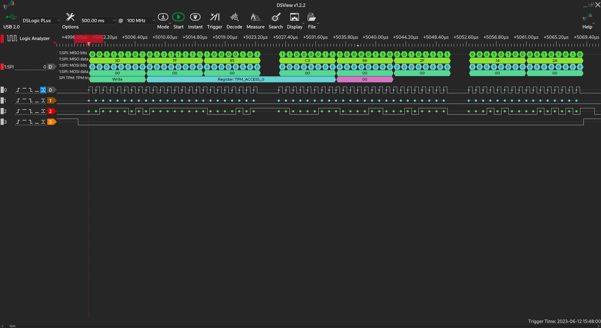
The transfer works properly at 100 KHz. At 10 MHz the transfer sometimes works,
sometimes does not:
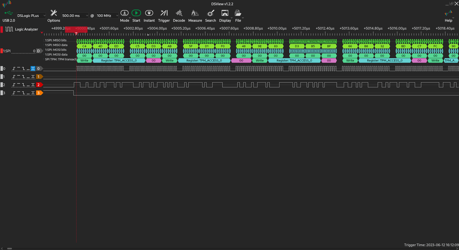
At 24 MHz transfer is completely corrupted. We have been looking for a solution
in Zephyr Issues and
Pull Requests but found
nothing useful.
Looking at Zephyr’s
SPI driver code, we discovered that every call to spi_write causes many things
to happen. Among others, the SPI controller is reconfigured
every single time.
During this process, the SPI controller is disabled and re-enabled, which is
quite suspicious.
Reading STM32 documentation
I’ve been searching through STM32 documentation for information about high-speed
SPI. The most helpful were the STM32L4 series programming manual and
AN5543.
Section 4.2 of AN5543
describes various aspects of handling high-speed communication, and section
4.2.2 describes what happens when SPI is disabled.
The main problem here is that Zephyr (as well as STM32 HAL) re-configures SPI
before each transaction, doing configure-enable-transmit-disable cycle on each
SPI session. While this is ok for master, slave must respect timings imposed
by master, so SPI disabling should be avoided if not needed.
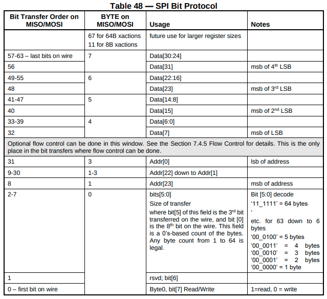
The problem becomes even more evident when we want to implement TPM protocol
as we don’t know size (and direction) of data payload. Each TPM frame starts
with a 4 byte header which tells us what is the size of transfer and what is the
direction (read from or write to a register):
After we read the header, we disable SPI, causing a few things:
- MISO is left floating (we have SPI v1.3 on STM32L4)
- we introduce additional delay by re-configuring SPI
Fixing SPI
We decided to continue the tests using only HAL and STM32CubeIDE (we plan to
port the solution back to Zephyr). From earlier tests, we already know that HAL
also does not work correctly, but it is easier to roll out a custom solution.
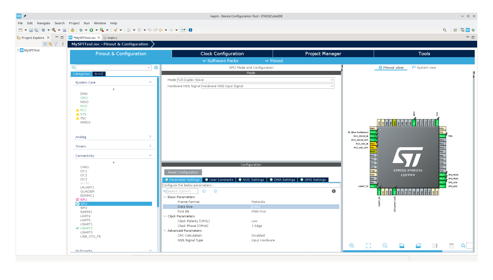
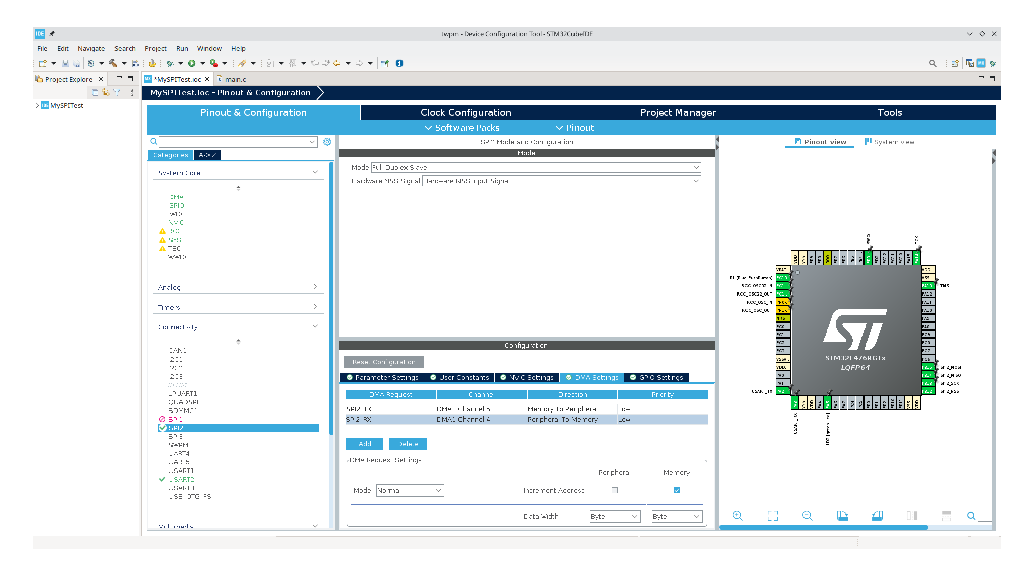
So, I created a new STM32CubeMX project and set up the SPI2 controller through
the graphical configuration manager. Basic settings involve configuring SPI as a
Full-Duplex Slave, configuring NSS (Chip Select) pin as input, setting 8-bit
frame length (as required by TPM spec), and setting up DMA channels. All other
settings are left at their defaults.
STM32CubeMX generates code that performs hardware initialization, and we are
ready to do SPI transactions using the HAL_SPI_TransmitReceive_DMA function.
Let’s look at the implementation:
  1
  2
  3
  4
  5
  6
  7
  8
  9
 10
 11
 12
 13
 14
 15
 16
 17
 18
 19
 20
 21
 22
 23
 24
 25
 26
 27
 28
 29
 30
 31
 32
 33
 34
 35
 36
 37
 38
 39
 40
 41
 42
 43
 44
 45
 46
 47
 48
 49
 50
 51
 52
 53
 54
 55
 56
 57
 58
 59
 60
 61
 62
 63
 64
 65
 66
 67
 68
 69
 70
 71
 72
 73
 74
 75
 76
 77
 78
 79
 80
 81
 82
 83
 84
 85
 86
 87
 88
 89
 90
 91
 92
 93
 94
 95
 96
 97
 98
 99
100
101
102
103
104
105
106
107
108
109
110
111
112
113
114
115
116
117
118
|
HAL_StatusTypeDef HAL_SPI_TransmitReceive_DMA(SPI_HandleTypeDef *hspi, uint8_t *pTxData, uint8_t *pRxData, uint16_t Size)
{
  ...

  /* Reset the threshold bit */
  CLEAR_BIT(hspi->Instance->CR2, SPI_CR2_LDMATX | SPI_CR2_LDMARX);

  /* The packing mode management is enabled by the DMA settings according the spi data size */
  if (hspi->Init.DataSize > SPI_DATASIZE_8BIT)
  {
    /* Set fiforxthreshold according the reception data length: 16bit */
    CLEAR_BIT(hspi->Instance->CR2, SPI_RXFIFO_THRESHOLD);
  }
  else
  {
    /* Set RX Fifo threshold according the reception data length: 8bit */
    SET_BIT(hspi->Instance->CR2, SPI_RXFIFO_THRESHOLD);

    if (hspi->hdmatx->Init.MemDataAlignment == DMA_MDATAALIGN_HALFWORD)
    {
      if ((hspi->TxXferSize & 0x1U) == 0x0U)
      {
        CLEAR_BIT(hspi->Instance->CR2, SPI_CR2_LDMATX);
        hspi->TxXferCount = hspi->TxXferCount >> 1U;
      }
      else
      {
        SET_BIT(hspi->Instance->CR2, SPI_CR2_LDMATX);
        hspi->TxXferCount = (hspi->TxXferCount >> 1U) + 1U;
      }
    }

    if (hspi->hdmarx->Init.MemDataAlignment == DMA_MDATAALIGN_HALFWORD)
    {
      /* Set RX Fifo threshold according the reception data length: 16bit */
      CLEAR_BIT(hspi->Instance->CR2, SPI_RXFIFO_THRESHOLD);

      if ((hspi->RxXferCount & 0x1U) == 0x0U)
      {
        CLEAR_BIT(hspi->Instance->CR2, SPI_CR2_LDMARX);
        hspi->RxXferCount = hspi->RxXferCount >> 1U;
      }
      else
      {
        SET_BIT(hspi->Instance->CR2, SPI_CR2_LDMARX);
        hspi->RxXferCount = (hspi->RxXferCount >> 1U) + 1U;
      }
    }
  }

  /* Check if we are in Rx only or in Rx/Tx Mode and configure the DMA transfer complete callback */
  if (hspi->State == HAL_SPI_STATE_BUSY_RX)
  {
    /* Set the SPI Rx DMA Half transfer complete callback */
    hspi->hdmarx->XferHalfCpltCallback = SPI_DMAHalfReceiveCplt;
    hspi->hdmarx->XferCpltCallback     = SPI_DMAReceiveCplt;
  }
  else
  {
    /* Set the SPI Tx/Rx DMA Half transfer complete callback */
    hspi->hdmarx->XferHalfCpltCallback = SPI_DMAHalfTransmitReceiveCplt;
    hspi->hdmarx->XferCpltCallback     = SPI_DMATransmitReceiveCplt;
  }

  /* Set the DMA error callback */
  hspi->hdmarx->XferErrorCallback = SPI_DMAError;

  /* Set the DMA AbortCpltCallback */
  hspi->hdmarx->XferAbortCallback = NULL;

  /* Enable the Rx DMA Stream/Channel  */
  if (HAL_OK != HAL_DMA_Start_IT(hspi->hdmarx, (uint32_t)&hspi->Instance->DR, (uint32_t)hspi->pRxBuffPtr,
                                 hspi->RxXferCount))
  {
    /* Update SPI error code */
    SET_BIT(hspi->ErrorCode, HAL_SPI_ERROR_DMA);
    errorcode = HAL_ERROR;

    hspi->State = HAL_SPI_STATE_READY;
    goto error;
  }

  /* Enable Rx DMA Request */
  SET_BIT(hspi->Instance->CR2, SPI_CR2_RXDMAEN);

  /* Set the SPI Tx DMA transfer complete callback as NULL because the communication closing
  is performed in DMA reception complete callback  */
  hspi->hdmatx->XferHalfCpltCallback = NULL;
  hspi->hdmatx->XferCpltCallback     = NULL;
  hspi->hdmatx->XferErrorCallback    = NULL;
  hspi->hdmatx->XferAbortCallback    = NULL;

  /* Enable the Tx DMA Stream/Channel  */
  if (HAL_OK != HAL_DMA_Start_IT(hspi->hdmatx, (uint32_t)hspi->pTxBuffPtr, (uint32_t)&hspi->Instance->DR,
                                 hspi->TxXferCount))
  {
    /* Update SPI error code */__HAL_SPI_ENABLE
    SET_BIT(hspi->ErrorCode, HAL_SPI_ERROR_DMA);
    errorcode = HAL_ERROR;

    hspi->State = HAL_SPI_STATE_READY;
    goto error;
  }

  /* Check if the SPI is already enabled */
  if ((hspi->Instance->CR1 & SPI_CR1_SPE) != SPI_CR1_SPE)
  {
    /* Enable SPI peripheral */
    __HAL_SPI_ENABLE(hspi);
  }
  /* Enable the SPI Error Interrupt Bit */
  __HAL_SPI_ENABLE_IT(hspi, (SPI_IT_ERR));

  /* Enable Tx DMA Request */
  SET_BIT(hspi->Instance->CR2, SPI_CR2_TXDMAEN);

  ...
}
|
What this code does:
- Initialize callbacks (like transfer complete callbacks)
- Configure SPI registers
- Initialize DMA channels and enable DMA on SPI controller (RXDMAEN and TXDMAEN
bits)
- Enable SPI interrupts
- Enable SPI controller
Many of these things could be done only once and never changed. Doing this every
time introduces additional overhead. Moreover, SPI is re-enabled before each
transaction and disabled after the transaction. This worsens the overhead and
causes other problems described in
AN5543:
SPI versions 1.x.x: the peripheral takes no control of the associated GPIOs
when it is disabled. The SPI signals float if they are not supported by
external resistor and if they are not reconfigured and they are kept at
alternate function configuration.
At principle, the SPI must not be disabled before the communication is fully
completed and it should be as short as possible at slave, especially between
sessions, to avoid missing any communication.
On Nucleo L476RG we use, we have SPI v1.3, which does not drive MISO when
disabled. We have observed MISO line changing unexpectedly during SPI idle
periods, presumably caused by this.
HAL_SPI_TransmitReceive_DMA setups interrupt callbacks which handle error
detection and the end-of-transaction condition (SPI_EndRxTxTransaction), which
involves waiting for the master to stop sending data and the SPI bus to become
idle. This causes more unnecessary overhead, as we don’t have to wait for SPI
idle. We can process data as soon as RX DMA completes and queue more data as
soon as TX DMA completes.
A transaction in the TPM protocol consists of three steps: TPM header
transmission, flow control, and data payload transmission. After receiving the
header, we know the size of the entire transaction, removing the need for
end-of-transaction checking.
I created a stripped-down version of HAL_SPI_TransmitReceive_DMA:
 1
 2
 3
 4
 5
 6
 7
 8
 9
10
11
12
13
14
15
16
17
18
19
20
21
22
23
24
25
26
27
28
29
30
31
32
33
34
35
|
static uint8_t tx_buf[4] = {0xaa, 0xe0, 0xbb, 0xa5};
static uint8_t rx_buf[4] = {0};

static void rxdma_complete(DMA_HandleTypeDef *hdma)
{
    SPI_HandleTypeDef *hspi = (SPI_HandleTypeDef *)(((DMA_HandleTypeDef *)hdma)->Parent);
    HAL_DMA_Start_IT(hspi->hdmarx, (uint32_t)&hspi->Instance->DR, (uint32_t)rx_buf, 4);
}

static void txdma_complete(DMA_HandleTypeDef *hdma)
{
    SPI_HandleTypeDef *hspi = (SPI_HandleTypeDef *)(((DMA_HandleTypeDef *)hdma)->Parent);
    HAL_DMA_Start_IT(hspi->hdmatx, (uint32_t)tx_buf, (uint32_t)&hspi->Instance->DR, 4);
}

void app_main() {
    SPI_HandleTypeDef *hspi = &hspi2;

    // Initialize callbacks
    hspi->hdmatx->XferCpltCallback = txdma_complete;
    hspi->hdmarx->XferCpltCallback = rxdma_complete;

    // One-time SPI configuration
    // Clear SPI_RXFIFO_THRESHOLD to trigger DMA on each byte available.
    CLEAR_BIT(hspi->Instance->CR2, SPI_RXFIFO_THRESHOLD);

    // Start the transfer
    SET_BIT(hspi->Instance->CR2, SPI_CR2_RXDMAEN);
    HAL_DMA_Start_IT(hspi->hdmarx, (uint32_t)&hspi->Instance->DR, (uint32_t)rx_buf, 4);

    HAL_DMA_Start_IT(hspi->hdmatx, (uint32_t)tx_buf, (uint32_t)&hspi->Instance->DR, 4);
    SET_BIT(hspi->Instance->CR2, SPI_CR2_TXDMAEN);

    __HAL_SPI_ENABLE(hspi);
}
|
The code size is reduced to almost a minimum - still, some optimizations could
be done in HAL_DMA_Start_IT. Currently, we transmit only 4 bytes of static
data to test whether MCU can handle this before going further.
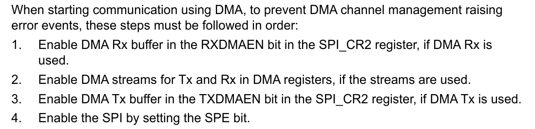
I’m using a bit different initialization sequence than HAL: HAL enables
RXDMAEN after programming the channel and TXDMAEN after enabling SPI. Our
code follows the sequence described in the STM32 Programming Manual (rm0351).
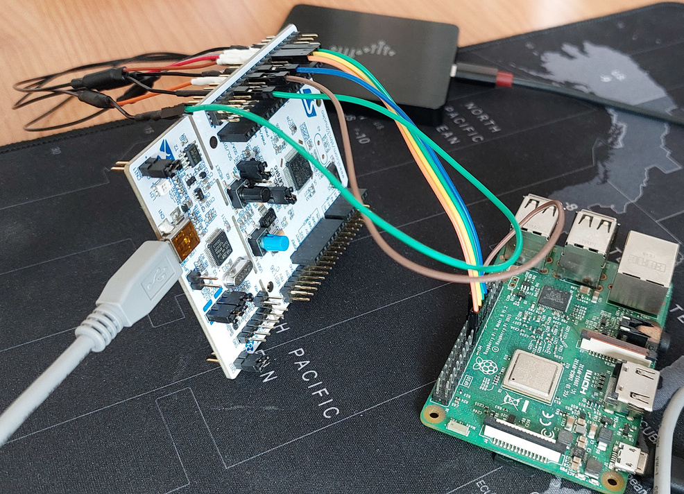
For testing purposes, I’m using Raspberry PI 3B as SPI host. Configuration is
pretty straightforward, you can enable spidev by uncommenting
dtoverlay=spi0-1cs in /boot/config.txt and rebooting. For communicating with
spidev I’m using a custom Python script:
 1
 2
 3
 4
 5
 6
 7
 8
 9
10
11
12
13
14
15
16
17
18
19
20
21
22
23
24
25
26
27
28
29
30
31
32
33
34
35
36
37
38
39
40
41
42
43
44
45
46
47
48
49
50
51
52
53
54
55
56
|
from spidev import SpiDev

class Spi:
    def __init__(self):
        self.device = SpiDev()
        self.device.open(0, 0)
        self.device.bits_per_word = 8
        self.device.mode = 0b00
        self.device.max_speed_hz = 24000000
        self.freq = 24000000

    def get_frequency(self):
        return self.freq

    def set_frequency(self, freq):
        self.freq = freq

    def xfer(self, data: bytes) -> bytes:
        return self.device.xfer(data, self.freq)


def test(func):
    def wrapper():
        freq = spi.freq
        iteration = 0

        try:
            for i in range(10):
                iteration = i
                func()
            print(f'OK: {func.__name__} @ {freq} Hz')
        except AssertionError:
            print(f'FAIL: {func.__name__} @ {freq} Hz (iteration {iteration})')
    return wrapper


@test
def test_read_constant_4byte():
    expected_data = [0xaa, 0xe0, 0xbb, 0xa5]
    result = spi.xfer([0xff] * len(expected_data))
    print('result = {:x} {:x} {:x} {:x}'.format(result[0], result[1], result[2], result[3]))
    assert result == expected_data


def main():
    global spi

    try:
        spi = Spi()
        spi.set_frequency(24000000)
        test_read_constant_4byte()
    finally:
        spi.device.close()

if __name__ == '__main__':
    main()
|
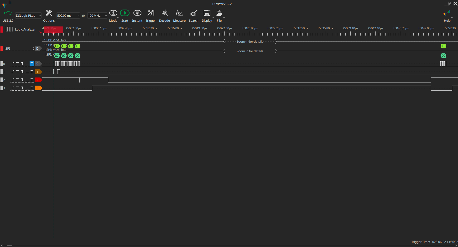
After running the test code, I saw the transmitted data was correct through the
logic analyzer, but Raspberry PI didn’t receive the right data. This was a
problem with the connection between Raspberry PI and Nucleo. I could achieve
stable transmission at frequencies up to 18 MHz. After changing cable
connections, I got stable transmission at 22 MHz. Before, I was using two 20 cm
male-to-female jumper wires for each SPI line. The cables and the logic analyzer
probes were connected to a breadboard. Now, I have a direct connection between
Nucleo and Raspberry using a single 20 cm female jumper wire for each line.
Nucleo pins stretch into two sides of the board, so I can attach the probes
directly on the backside of Nucleo.
The work continues - implementing TPM protocol
While 22 MHz is not the frequency we aim for, I continued tests on the highest
frequency I could afford for now (in the meantime planning to replace the cables
with better ones). I extended the code to speak over the TPM protocol
 1
 2
 3
 4
 5
 6
 7
 8
 9
10
11
12
13
14
15
16
17
18
19
20
21
22
23
24
25
26
27
28
29
30
31
32
33
34
35
36
37
38
39
40
41
42
43
44
45
46
47
48
49
50
51
52
53
54
55
56
57
58
59
60
61
62
63
64
65
66
67
68
69
70
71
72
73
74
75
76
77
78
79
80
|
#define STATE_WAIT_HEADER 0
#define STATE_WAIT_STATE 1
#define STATE_WAIT_STATE_LAST 2
#define STATE_PAYLOAD_TRANSFER 3

static uint8_t ff_buffer[64];
static uint8_t waitstate_insert[4] = {0xff, 0xff, 0xff, 0xfe};
static uint8_t waitstate_hold[1] = {0x00};

static uint8_t waitstate_cancel[1] = {0x01};
static uint8_t trash[1] = {0};
static uint8_t header[4] = {0};
static bool b_txdma_complete = false;
static bool b_rxdma_complete = false;
static uint8_t state = STATE_WAIT_HEADER;

static uint8_t scratch_buffer[64] = {0};

static uint8_t transfer_is_read = 0;
static uint32_t transfer_length = 0;

static void update_state(SPI_HandleTypeDef *hspi)
{
    b_rxdma_complete = false;
    b_txdma_complete = false;

    switch (state) {
    case STATE_WAIT_HEADER:
        // We don't care what host sends during wait state, but we start DMA anyway to avoid overrun errors.
        HAL_DMA_Start_IT(hspi->hdmarx, (uint32_t)&hspi->Instance->DR, (uint32_t)trash, sizeof trash);
        // Wait state got inserted while reading header.
        HAL_DMA_Start_IT(hspi->hdmatx, (uint32_t)waitstate_cancel, (uint32_t)&hspi->Instance->DR, sizeof waitstate_cancel);

    // This follows a real TPM protocol, except we ignore addr currently.
        transfer_is_read = !!(header[0] & (1 << 7));
        transfer_length = (header[0] & 0x3f) + 1;
    // Remaining bytes contain TPM register offset. Currently we have only one
    // "register" so we just ignore that.

        state = STATE_WAIT_STATE_LAST;
        break;

    case STATE_WAIT_STATE_LAST:
        if (transfer_is_read) {
            HAL_DMA_Start_IT(hspi->hdmatx, (uint32_t)scratch_buffer, (uint32_t)&hspi->Instance->DR, transfer_length);
            HAL_DMA_Start_IT(hspi->hdmarx, (uint32_t)&hspi->Instance->DR, (uint32_t)ff_buffer, transfer_length);
        } else {
            HAL_DMA_Start_IT(hspi->hdmatx, (uint32_t)ff_buffer, (uint32_t)&hspi->Instance->DR, transfer_length);
            HAL_DMA_Start_IT(hspi->hdmarx, (uint32_t)&hspi->Instance->DR, (uint32_t)scratch_buffer, transfer_length);
        }

        state = STATE_PAYLOAD_TRANSFER;
        break;

    case STATE_PAYLOAD_TRANSFER:
        HAL_DMA_Start_IT(hspi->hdmarx, (uint32_t)&hspi->Instance->DR, (uint32_t)header, sizeof header);
        HAL_DMA_Start_IT(hspi->hdmatx, (uint32_t)waitstate_insert, (uint32_t)&hspi->Instance->DR, sizeof waitstate_insert);

        state = STATE_WAIT_HEADER;
        break;
    }
}

static void rxdma_complete(DMA_HandleTypeDef *hdma)
{
    SPI_HandleTypeDef *hspi = (SPI_HandleTypeDef *)(((DMA_HandleTypeDef *)hdma)->Parent);
    if (b_txdma_complete)
        update_state(hspi);
    else
        b_rxdma_complete = true;
}

static void txdma_complete(DMA_HandleTypeDef *hdma)
{
    SPI_HandleTypeDef *hspi = (SPI_HandleTypeDef *)(((DMA_HandleTypeDef *)hdma)->Parent);
    if (b_rxdma_complete)
        update_state(hspi);
    else
        b_txdma_complete = true;
}
|
On Python side I introduce a new function:
 1
 2
 3
 4
 5
 6
 7
 8
 9
10
11
12
13
14
15
16
17
18
19
|
def tpm_read(size: int) -> bytes:
    assert size > 0 and size <= 64

    header = bytes([
        (1 << 7) | (size - 1),
        0, 0, 0
    ])

    waitstate = spi.xfer(header)
    assert waitstate == [0xff, 0xff, 0xff, 0xfe]

    while True:
        status = spi.xfer([0])
        if status[0] == 1:
            break
        assert status[0] == 0

    empty = [0] * size
    return spi.xfer(empty)
|
And update the test:
1
2
3
4
|
@test
def test_read():
    x = tpm_read(0, 8)
    assert x == [0] * 8
|
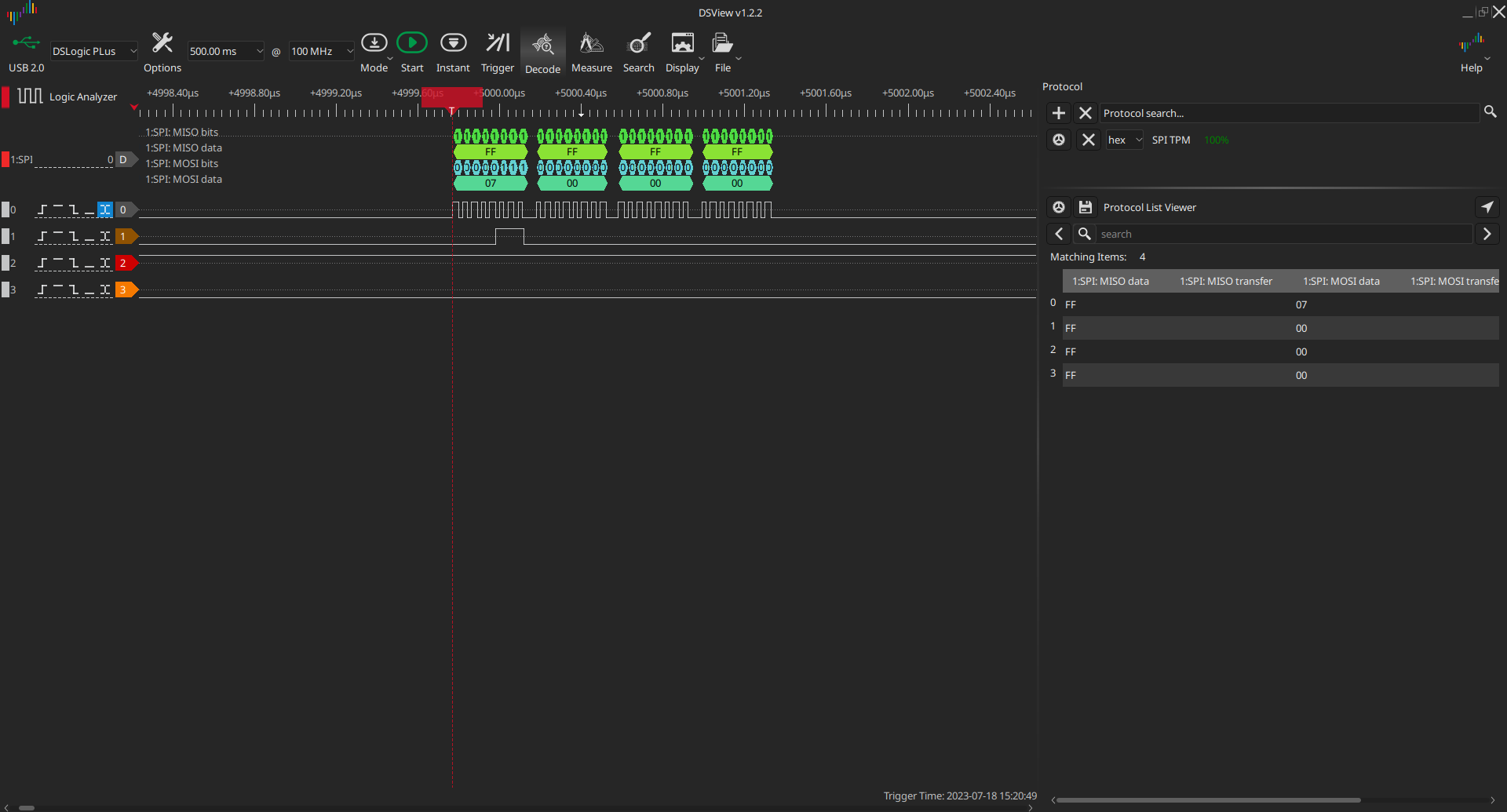
After running the test code, I immediately got an error, the logic analyzer
showing:
There are two problems here. The first problem is that the CS pin goes high
between the header, wait states, and payload. This was my oversight, but fixing
it is not critical as it currently does not affect communication - deasserting
the CS pin should abort the transaction, but we don’t handle this yet. Linux’s
spidev drivers can be instructed not to deassert CS, but this is not supported
by the bindings I’m using, so let’s just postpone the fix.
The other problem is with the transmission itself - Nucleo transmits wrong data
(0xff) instead of 0x01 during the wait state.
To solve the problem, I went a step back. I hardcoded a few data patterns to
replicate the transfer sequence:
 1
 2
 3
 4
 5
 6
 7
 8
 9
10
11
12
13
14
15
16
17
18
19
20
21
22
23
24
25
26
27
28
29
30
31
32
33
34
35
36
37
38
39
40
41
42
|
struct pattern {
    uint8_t *data;
    uint8_t len;
};

#define ARRAY_SIZE(x) (sizeof((x)) / sizeof((x)[0]))

static uint8_t pattern_0[] = {0xff, 0xff, 0xff, 0xfe};
static uint8_t pattern_1[] = {1};
static uint8_t pattern_2[] = {
    0x3e, 0x60, 0xc3, 0x4f, 0x35, 0x2e, 0xa6, 0xaa, 0xa6, 0x61, 0x64, 0xcb,
    0x10, 0xd7, 0x45, 0x35, 0x82, 0xc9, 0x91, 0xbc, 0x35, 0x43, 0xbb, 0xe1,
    0xea, 0x08, 0xdf, 0xdd, 0x4d, 0xd8, 0xd5, 0x94, 0x71, 0x75, 0xfd, 0x23,
    0x24, 0xf8, 0x95, 0x85, 0x7b, 0x11, 0xf9, 0xdd, 0xa0, 0xaa, 0x60, 0xc5,
    0xd2, 0x07, 0x6b, 0x3a, 0xd4, 0xd2, 0xac, 0xac, 0x1b, 0x54, 0xfe, 0x2f,
    0xa2
};

static struct pattern patterns[] = {
    { .data = pattern_0, .len = sizeof pattern_0 },
    { .data = pattern_1, .len = sizeof pattern_1 },
    { .data = pattern_2, .len = sizeof pattern_2 },
};
int current_pattern = 1;

static void txdma_complete(DMA_HandleTypeDef *hdma)
{
    SPI_HandleTypeDef *hspi = (SPI_HandleTypeDef *)(((DMA_HandleTypeDef *)hdma)->Parent);
    HAL_DMA_Start_IT(hspi->hdmatx, (uint32_t)patterns[current_pattern].data, (uint32_t)&hspi->Instance->DR, patterns[current_pattern].len);

    if (++current_pattern == ARRAY_SIZE(patterns))
        current_pattern = 0;
}

void app_main() {
    hspi->hdmatx->XferCpltCallback = txdma_complete;

    HAL_DMA_Start_IT(hspi->hdmatx, (uint32_t)pattern_0, (uint32_t)&hspi->Instance->DR, sizeof pattern_0);
    SET_BIT(hspi->Instance->CR2, SPI_CR2_TXDMAEN);

    __HAL_SPI_ENABLE(hspi);
}
|
And on Python side:
 1
 2
 3
 4
 5
 6
 7
 8
 9
10
11
12
13
14
15
16
17
18
19
20
21
|
patterns = [
    [0xff, 0xff, 0xff, 0xfe],
    [0x01],
    [
        0x3e, 0x60, 0xc3, 0x4f, 0x35, 0x2e, 0xa6, 0xaa, 0xa6, 0x61, 0x64, 0xcb,
        0x10, 0xd7, 0x45, 0x35, 0x82, 0xc9, 0x91, 0xbc, 0x35, 0x43, 0xbb, 0xe1,
        0xea, 0x08, 0xdf, 0xdd, 0x4d, 0xd8, 0xd5, 0x94, 0x71, 0x75, 0xfd, 0x23,
        0x24, 0xf8, 0x95, 0x85, 0x7b, 0x11, 0xf9, 0xdd, 0xa0, 0xaa, 0x60, 0xc5,
        0xd2, 0x07, 0x6b, 0x3a, 0xd4, 0xd2, 0xac, 0xac, 0x1b, 0x54, 0xfe, 0x2f,
        0xa2
    ]
]

spi = Spi()
spi.set_frequency(22000000)

for i in range(100000):
    for pattern in patterns:
        data = spi.xfer([0] * len(pattern))
        print(f'iter {i} test {data} == {pattern}')
        assert data == pattern
|
The code works just fine (100k iterations)
1
2
3
4
5
|
...
iter 99999 test [255, 255, 255, 254] == [255, 255, 255, 254]
iter 99999 test [1] == [1]
iter 99999 test [62, 96, 195, 79, 53, 46, 166, 170, 166, 97, 100, 203, 16, 215, 69, 53, 130, 201, 145, 188, 53, 67, 187, 225, 234, 8, 223, 221, 77, 216, 213, 148, 113, 117, 253, 35, 36, 248, 149, 133, 123, 17, 249, 221,
160, 170, 96, 197, 210, 7, 107, 58, 212, 210, 172, 172, 27, 84, 254, 47, 162] == [62, 96, 195, 79, 53, 46, 166, 170, 166, 97, 100, 203, 16, 215, 69, 53, 130, 201, 145, 188, 53, 67, 187, 225, 234, 8, 223, 221, 77, 216, 213, 148, 113, 117, 253, 35, 36, 248, 149, 133, 123, 17, 249, 221, 160, 170, 96, 197, 210, 7, 107, 58, 212, 210, 172, 172, 27, 84, 254, 47, 162]
|
The main difference is that the full code performs reading and writing, contrary
to only writing. Currently, we wait for both TX and RX DMA to complete before
re-programming DMA channels and updating the state machine. TX and RX are always
the same size, so they should complete in a similar time. So, instead of using
interrupts for both channels, I changed the code so that interrupts are used for
TX and polling for RX (tests showed that TX DMA usually completes first).
 1
 2
 3
 4
 5
 6
 7
 8
 9
10
11
12
13
14
15
16
17
18
19
20
21
22
23
24
25
26
27
28
29
30
31
32
33
34
35
36
37
38
39
40
41
42
|
static void txdma_complete(DMA_HandleTypeDef *hdma)
{
    SPI_HandleTypeDef *hspi = (SPI_HandleTypeDef *)(((DMA_HandleTypeDef *)hdma)->Parent);

    switch (state) {
    case STATE_WAIT_HEADER:
        // Wait state got inserted while reading header.
        HAL_DMA_Start_IT(hspi->hdmatx, (uint32_t)waitstate_cancel, (uint32_t)&hspi->Instance->DR, sizeof waitstate_cancel);

        // We don't care what host sends during wait state, but we start DMA anyway to avoid overrun errors.
        HAL_DMA_PollForTransfer(hspi->hdmarx, HAL_DMA_FULL_TRANSFER, HAL_MAX_DELAY);
        HAL_DMA_Start_IT(hspi->hdmarx, (uint32_t)&hspi->Instance->DR, (uint32_t)trash, sizeof trash);

        transfer_is_read = !!(header[0] & (1 << 7));
        transfer_length = (header[0] & 0x3f) + 1;

        state = STATE_WAIT_STATE_LAST;
        break;

    case STATE_WAIT_STATE_LAST:
        if (transfer_is_read) {
            HAL_DMA_Start_IT(hspi->hdmatx, (uint32_t)scratch_buffer, (uint32_t)&hspi->Instance->DR, transfer_length);
            HAL_DMA_PollForTransfer(hspi->hdmarx, HAL_DMA_FULL_TRANSFER, HAL_MAX_DELAY);
            HAL_DMA_Start_IT(hspi->hdmarx, (uint32_t)&hspi->Instance->DR, (uint32_t)ff_buffer, transfer_length);
        } else {
            HAL_DMA_Start_IT(hspi->hdmatx, (uint32_t)ff_buffer, (uint32_t)&hspi->Instance->DR, transfer_length);
            HAL_DMA_PollForTransfer(hspi->hdmarx, HAL_DMA_FULL_TRANSFER, HAL_MAX_DELAY);
            HAL_DMA_Start_IT(hspi->hdmarx, (uint32_t)&hspi->Instance->DR, (uint32_t)scratch_buffer, transfer_length);
        }

        state = STATE_PAYLOAD_TRANSFER;
        break;

    case STATE_PAYLOAD_TRANSFER:
        HAL_DMA_Start_IT(hspi->hdmatx, (uint32_t)waitstate_insert, (uint32_t)&hspi->Instance->DR, sizeof waitstate_insert);
        HAL_DMA_PollForTransfer(hspi->hdmarx, HAL_DMA_FULL_TRANSFER, HAL_MAX_DELAY);
        HAL_DMA_Start_IT(hspi->hdmarx, (uint32_t)&hspi->Instance->DR, (uint32_t)header, sizeof header);

        state = STATE_WAIT_HEADER;
        break;
    }
}
|
I start the TX transfer first, then poll for RX DMA completion before
re-programming the DMA channel. Now, the test succeeds.
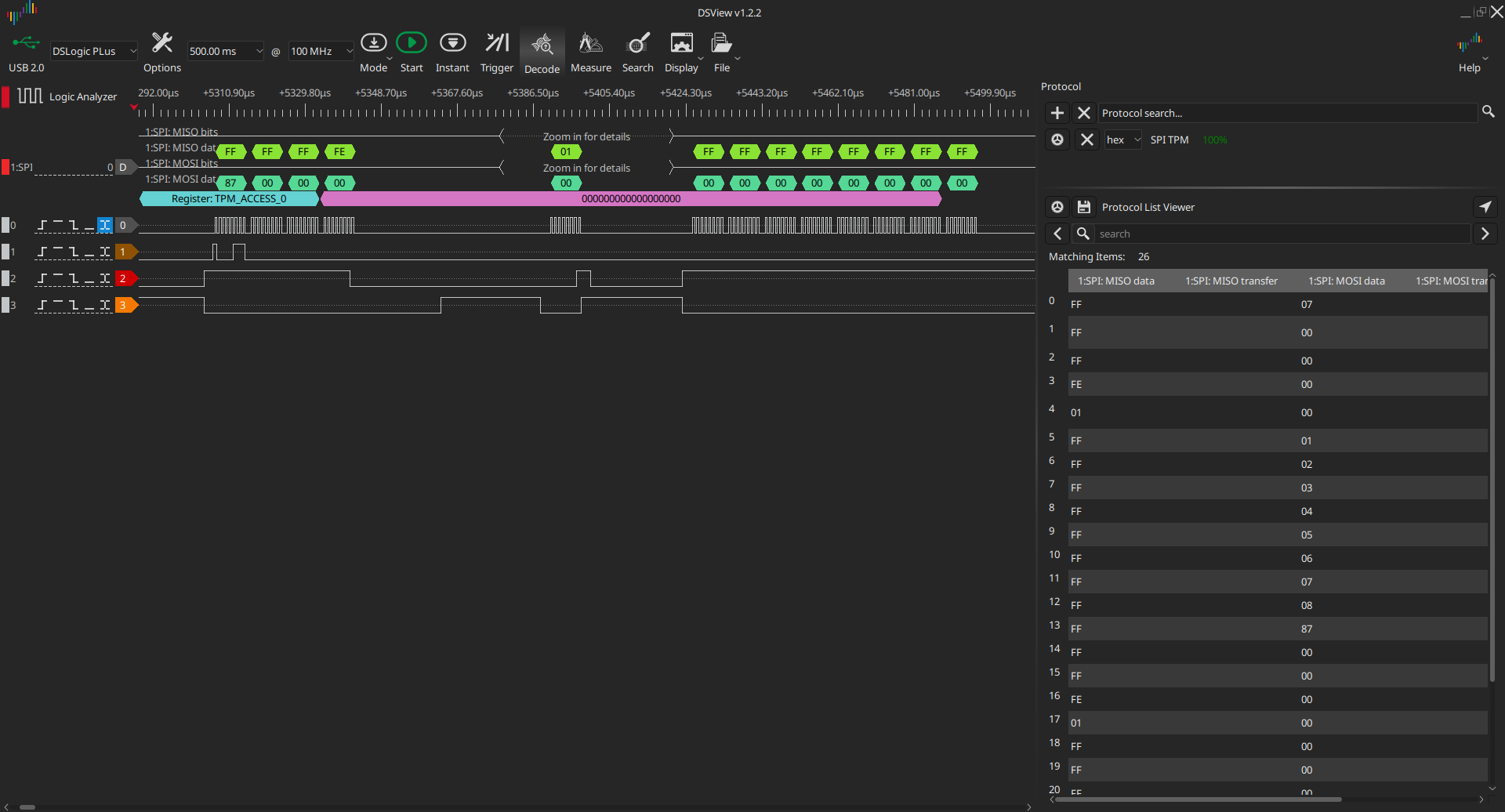
Extending tests
I have basic code that can read and write data over SPI, but I have tested only
read of a zeroed register. Now, it is time to extend the tests so that we write
random data of random lengths, then read the data back and check whether it is
as expected. I already got shorter cables - 10 cm instead of 20 cm,
and I have stable communication at 24 MHz:
I started with something simple
1
2
3
|
tpm_write(0, bytes([1,2,3,4,5,6,7,8]))
x = tpm_read(0, 8)
assert x == [1,2,3,4,5,6,7,8]
|
and failed. The first transfer succeeded, but the second did not:
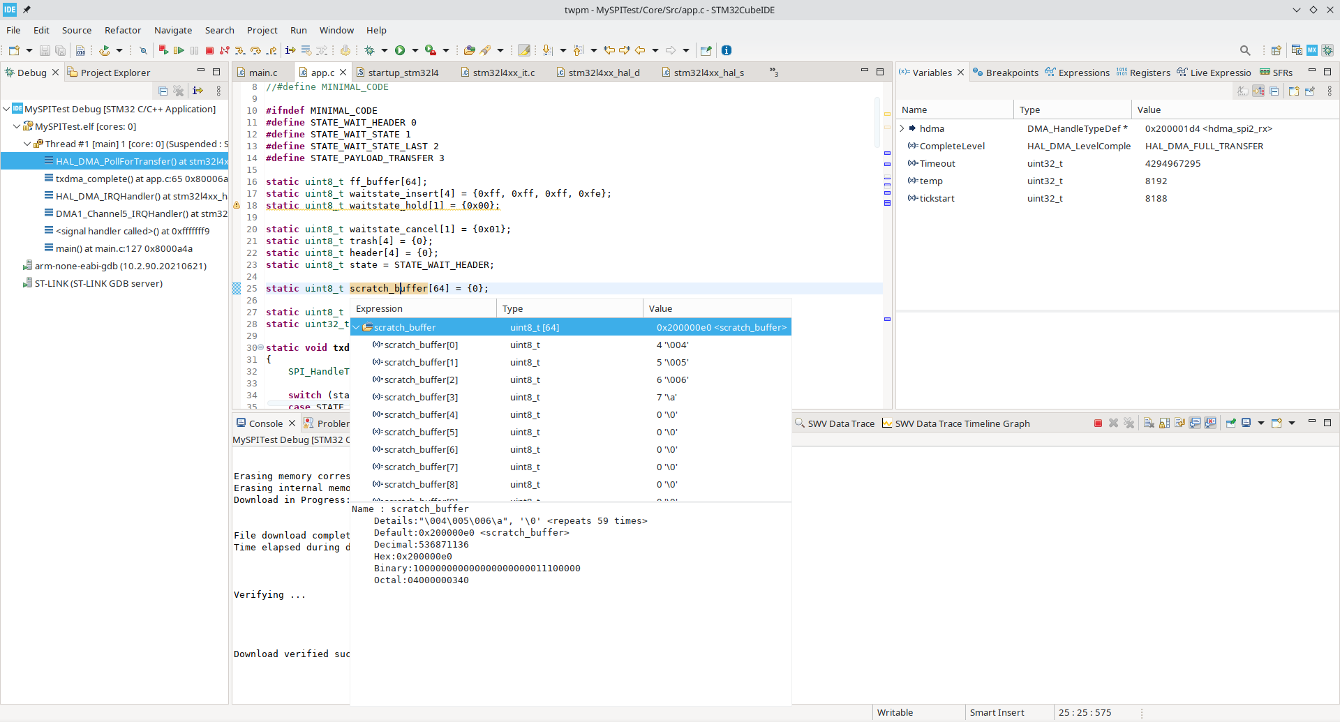
I hooked the debugger and saw that app was still polling for RX DMA completion.
Looking again at the original code, I found that I incorrectly cleared
SPI_RXFIFO_THRESHOLD bit - it should be clear for 16-bit frame length and set
for 8-bit frame length.
Changing
1
|
CLEAR_BIT(hspi->Instance->CR2, SPI_RXFIFO_THRESHOLD);
|
to
1
|
SET_BIT(hspi->Instance->CR2, SPI_RXFIFO_THRESHOLD);
|
solved the problem, however I got another one.
The wait state is properly inserted and terminated, but the payload is invalid.
I split the test into two to pause the app between write and read from the
register. Peeking at the scratch_buffer reveals that DMA went wrong, as the
first three bytes were lost entirely.
Moreover, we are again stuck polling for DMA completion (DMA is still waiting
for the remaining three bytes). The issue could be caused by too high delays
between restarting of DMA transfers, so I lowered the SPI frequency to 100 KHz,
but to my surprise, the result was exactly the same. I tested different data
sizes, and the result was always the same (3 bytes lost). So, the
SPI_RXFIFO_THRESHOLD fix only moved the problem a bit further. The outcome is
still the same.
Summary
That’s all for this blog post. I got SPI working at 24 MHz when writing, but
reading is broken. This is a significant improvement. I can’t tell whether SPI
could work at 24 MHz on that platform - even though it works for write, it
doesn’t mean it would work for reads and writes simultaneously. Further work
could include fixing RX on the current platform, but we could also try using
different platforms. We could try newer STM32 CPUs with a more recent SPI
version (and possibly a higher clock frequency), such as the STM32L5 series or
the latest STM32U5 series.
Further work will surely include implementing missing features, such as SPI bus
aborts, SPI synchronization (using CS pin), and error recovery. Also, some
patches may be needed for Zephyr due to suboptimal handling of SPI transactions.
Possibly, on a faster CPU, we could achieve 24 MHz without any problems, but we
could run into similar issues trying to work at the optional 66 MHz frequency.
Also, Zephyr’s SPI API currently doesn’t support transmission of variable-length
frames. There is an open RFC
issue that covers
API changes and optimized SPI handling to enable the usage of protocols
requiring them, so our future work could also include working on API
improvements. Lastly, we plan to upstream all Zephyr patches (if any).
The code for STM32 application is available
here.
Artur Kowalski
Junior embedded developer at 3mdeb. Interested in low-level development ranging from microcontroller programming to hypervisor and kernel development. In free time working on various personal open-source projects.