Introduction
ASRock Rack SPC741D8 is a server motherboard supporting Intel Sapphire Rapids series of processors. In this blog post we will be discussing the process of porting Dasharo to the platform and talk about the challenges we faced in the process. We will also be talking about the Dasharo Hardware Certification process and how to ensure a board passes it.
We gratefully acknowledge the Operating Systems Group at Karlsruhe Institute of Technology (Fabian Meyer, Felix Zimmer, Yussuf Khalil) for their contribution in initiating the coreboot port for this platform and supporting open-source firmware development.
This project consisted of taking the coreboot port created by the Operating Systems Group at KIT (merged upstream), backporting it to our coreboot fork which is currently based on slightly older coreboot release 24.12, resolving major bugs and enabling Dasharo firmware features, such as:
- SMM BWP flash protection
- UEFI Secure Boot integration
- CBFS Verification
- iPXE network boot
- Self encrypting drive support
- Setup menu password
- USB stack disable option
- Network stack disable option
- PCIe configuration menu
- UEFI RAM Disk support
- Firmware Update Mode
Additionally, the board was subjected to the same certification routine that all our releases are subjected to. This includes automated (where possible) and manual tests of the firmware interface and various OSes.
A pre-built reference system with Dasharo Pro Package is available on our store: link. Check it out if you are interested in servers running open-source firmware!
The motherboard
ASRock Rack SPC741D8-2L2T/BCM is a full-fledged single socket server board supporting Intel Sapphire Rapids and Emerald Rapids processors. It has a CEB (12" x 10.5") form factor, 8 DIMM slots 4 PCIe 5.0 / CXL 1.1 slots and four network interface adapters (2x 10GbE and 2x 1GbE).
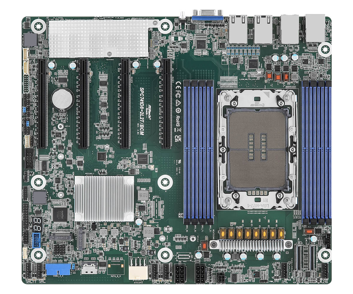
The name SPC741D8-2L2T/BCM indicates the following specifications:
- Intel C741 Platform Controller Hub
- CEB mainboard form factor
- 2x Broadcom 10GbE network interfaces
Like most server boards, it also features a baseboard management controller (BMC) chip responsible for remote management features. The BMC is an ASPEED AST2600 chip which is currently running proprietary AMI MegaRAC firmware. MegaRAC allows for remote keyboard, video and mouse (KVM) and supports full remote control of the platform, including flashing the BIOS or power management. We are evaluating the possibility of porting OpenBMC to it, but that is a matter for another blog post.
Flashing coreboot
The initial critical challenge involved integrating the existing coreboot port onto the target server platform. This particular board utilizes a 64 MB SOIC-16 form factor Serial Peripheral Interface (SPI) flash chip for its non-volatile firmware storage. This single chip is partitioned to house not only the platform’s traditional BIOS/UEFI firmware but also the firmware for the Intel Server Platform Services (Intel SPS), which is the server counterpart to the Intel Management Engine (ME).
Our first approach to flashing was leveraging the platform’s Baseboard Management Controller (BMC). Modern server BMCs often include a built-in feature for in-band or out-of-band firmware updates. We attempted to use the BMC’s proprietary BIOS flashing feature to write our coreboot image. However, this attempt was unsuccessful; the BMC’s firmware, designed to enforce compatibility, rejected the coreboot image, failing to recognize it as a valid, signed, or correctly structured BIOS binary from the Original Equipment Manufacturer (OEM).
Given that this server platform was slated for installation within the Dasharo Hardware Certification Lab, ensuring robust, reliable, and remote-accessible BIOS flashing capability was paramount for continuous development and debugging. The BMC’s rejection necessitated a shift to a hardware-level flashing solution. We opted to deploy a specialized Remote Testing Environment (RTE) board, which provides a crucial physical interface, allowing us to connect directly to the target board’s BIOS SPI flash chip.
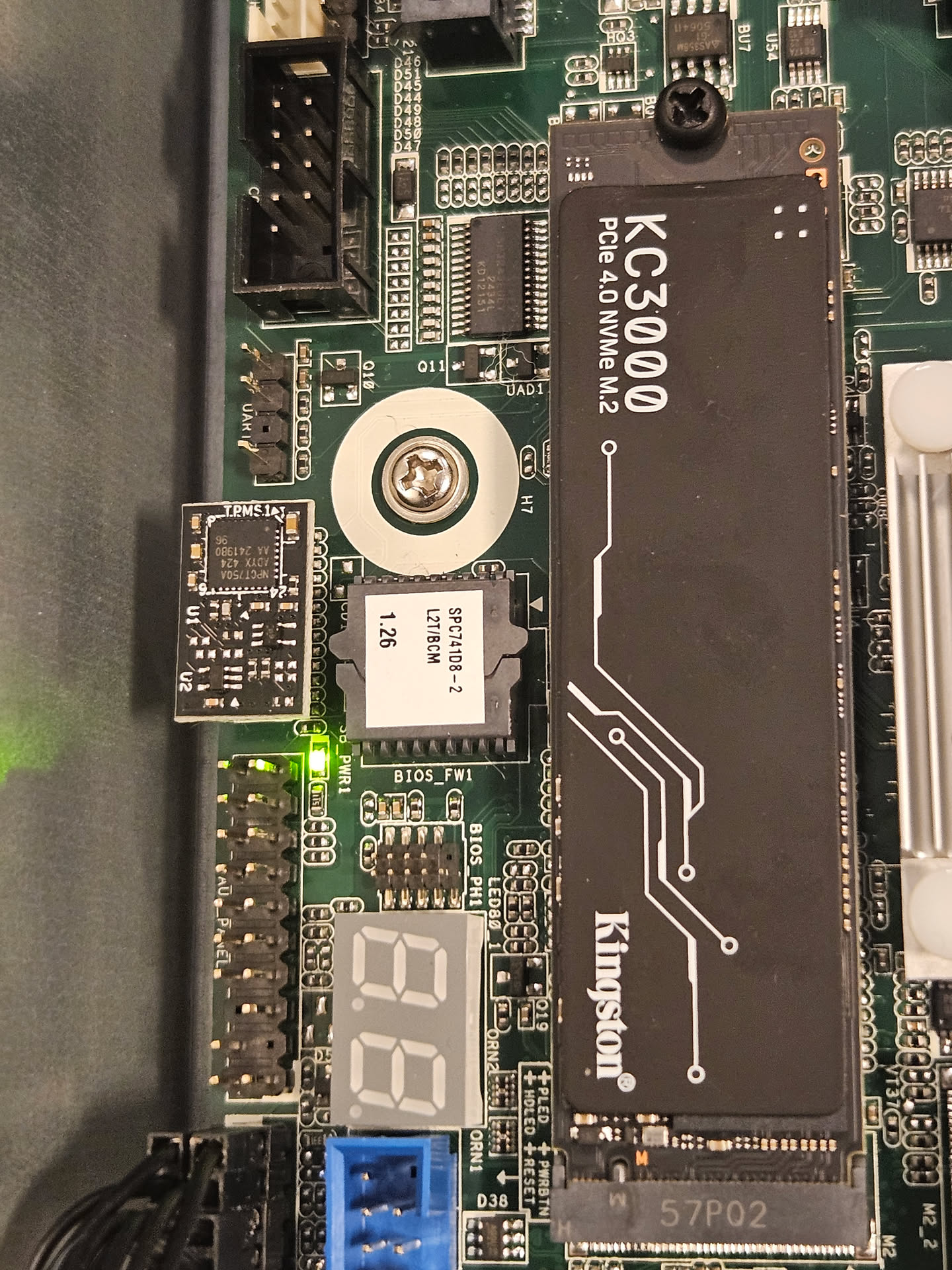
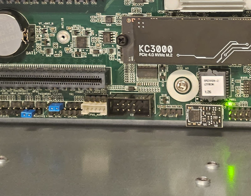
A minor physical hurdle presented itself: the BIOS chip was socketed rather than soldered, which, counterintuitively, prevented the simple application of a standard Pomona-style flashing clip for quick, non-invasive connection. Fortunately, the manufacturer, ASRock, provided an undocumented yet accessible BIOS_PH1 header. This header was strategically positioned to expose all the necessary SPI signals (CS#, SCK, MOSI, MISO, and power) required for direct flashing. Our task then became a process of reverse engineering the pinout of this proprietary header and sourcing or fabricating an appropriate adapter cable.
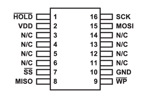
To determine the correct connection mapping, we utilized a multimeter to systematically probe each pin on the adapter cable against the eight signal pads on the socketed SOIC-16 SPI flash chip. The pin assignments of a standard SOIC-16 SPI flash are crucial for this process:
The BIOS_PH1 header is clearly visible next to the socketed BIOS chip on the board:
In the future, we plan to make make our own adapter cable with a ASRock
BIOS_PH1 header on one end and a standard SPI pinout on the other. This will
allow easier flashing and should simplify the laboratory setup process.
With the SPI connection established via the reconfigured cable, we finalized the RTE setup. This involved connecting a serial cable for low-level console access, an Ethernet cable for networking and remote control of the RTE itself, and a power button signal wire. This comprehensive connection suite grants us full remote control over the platform, encompassing low-level flashing, power cycling, and serial debugging, which is essential for expediting firmware development and testing cycles.
The lab assembly process has been documented here.
To summarize, the platform now fulfills the core criteria of the Dasharo Hardware Certification Lab:
- Power control (PSU via Sonoff, power button via GPIO on the RTE)
- Flashing of the BIOS chip
- Serial console available, for testing and debugging
Enabling the serial port
A critical requirement for low-level platform development is a functional serial port. This interface is the most reliable tool for debugging, providing a direct, OS-agnostic text stream from the earliest stages of the boot process - long before any graphics, USB, or networking drivers are loaded.
Our board features physical serial port headers, but they weren’t working out of the box. We knew these ports were not simple, “legacy” devices. Instead, they are managed by the Baseboard Management Controller (BMC) - in this case, an AST2600. The BMC is essentially a small, independent computer on the motherboard that provides powerful out-of-band management features like remote power control, KVM, and Serial over LAN.
This BMC chip communicates with the main CPU/PCH (Platform Controller Hub) using the Enhanced SPI (eSPI) bus. This modern, high-speed serial bus is the successor to the older LPC bus, and it’s responsible for connecting the PCH to platform peripherals like the BMC and Super I/O chips.
Our investigation into why the ports were dead led us to a crucial comment in a related code review:
|
|
This was a major revelation. The problem wasn’t simple configuration; it was a fundamental hardware topology issue.
Here’s what this means: The eSPI bus can have multiple devices, which are selected using different “Chip Select” (CS) lines.
|
|
The challenge was to tell the PCH that the I/O addresses for the standard serial ports (e.g., 0x3F8 for COM1, 0x2F8 for COM2) shouldn’t be ignored or sent to CS0#, but rather decoded and routed to the CS1# pin, where the BMC was listening.
After digging through PCH datasheets and related coreboot code, we found our “Rosetta Stone”: a PCI configuration register within the PCH’s LPC/eSPI controller, often named something like ESPI_CS1_ENABLE. This register’s entire job is to control this exact I/O decoding for the secondary eSPI bus.
It turns out that the solution was surprisingly simple. The existing coreboot code already had a variable, lpcioe, which was a bitmask of I/O ports to enable (COM1, COM2, and the Super I/O ports 0x4E/0x4F). We just needed to tell the PCH to apply this same bitmask to the CS1# bus.
The final patch was incredibly small but surgically precise:
|
|
The new line, pci_write_config16(PCH_DEV_LPC, ESPI_CS1_ENABLE, lpcioe);,
explicitly instructs the PCH: “Take that bitmask of serial ports (lpcioe) you
just enabled, and duplicate that enabling logic for the secondary eSPI chip
select (ESPI_CS1_ENABLE).”
With this change, the PCH’s internal I/O router was correctly configured. As the system booted, any data written to the 0x3F8 I/O port was now correctly forwarded over the eSPI bus to the CS1# pin, where the AST2600 BMC was waiting for it.
The result was a fully functional set of serial ports. We gained access to the physical COM header for direct debugging via the RTE and simultaneously enabled the BMC’s Serial over LAN (SOL) feature - a massive win for remote development and debugging.
Booting Windows
One of the more significant hurdles we encountered was getting Windows 11 to boot on our platform. A well-known and non-negotiable prerequisite for Windows 11 is the presence of a TPM 2.0 (Trusted Platform Module). This security chip is fundamental to Windows 11’s security model, powering features like BitLocker and Windows Hello.
Our board was physically equipped with a TPM 2.0 module. Our first diagnostic step was to boot into Linux, and sure enough, the kernel detected it instantly. We could interact with it, proving the hardware itself was fully functional.
However, the Windows 11 installer told a different story. Every installation attempt would halt with the infamous error: “This PC can’t run Windows 11.” The logs confirmed its complaint: it could not detect a valid TPM. This was a classic “it-works-in-Linux” mystery, which almost always points to a problem not with the hardware, but with how the firmware is describing the hardware to the operating system.
The investigation led us deep into coreboot and the ACPI (Advanced Configuration and Power Interface) tables. ACPI is the low-level language that firmware uses to tell an OS what hardware is present and where to find it. For the OS to “see” the TPM, it needs to be described at the correct ACPI device path-think of it as a file-system path for system hardware.
We found the culprit: a hardcoded path in the coreboot source code.
|
|
This path tells the OS, “Look for the TPM under the main System Bus (SB) and specifically on the first PCI bus (PCI0).”
On 99% of consumer platforms-laptops, desktops, and standard motherboards-this assumption is perfectly fine. These systems are single-domain, meaning they have one CPU package and a straightforward, predictable hardware layout. The TPM is almost always attached to this primary PCI bus.
Our board has one CPU socket, but it uses Intel`s Sapphire Rapids server platform, which supports multi-socket systems. In these systems, each socket can expose its own PCIe root bus (PCI0, PCI1, …). Our code hard-coded PCI0, so Windows looked in the wrong place. The fix is to discover the correct PCI root from ACPI instead of hard-coding it.
The correct ACPI path in our case should evaluate to:
|
|
To achieve this intelligently, the code was refactored to:
|
|
This new code is far more robust.
|
|
This logic works perfectly on both platform types. On a single-domain SoC, it resolves to the specific path Windows expects. On our multi-domain SoC, it provides the correct, more general path that allows Windows to properly discover the hardware regardless of which socket’s bus it’s on.
With this change made to the firmware, the Windows 11 installer booted, immediately recognized the TPM 2.0 module, and the installation proceeded without a single issue. It was a textbook example of how server-grade hardware complexities can break assumptions baked into code designed for simpler, consumer platforms.
Summary
All in all, thanks to the work done by the KIT OS Group, enabling Dasharo on this platform turned out to be simpler than if we were doing it from scratch. For that reason, we are thankful for their contribution to the open-source firmware community. As for Dasharo, we have released version v0.9.0, and a reference build is available in our shop. Check it out if you are interested in open-source firmware powered servers!
Unlock the full potential of your hardware and secure your firmware with the
experts at 3mdeb! If you’re looking to boost your product’s performance and
protect it from potential security threats, our team is here to help. Schedule
a call with
us or
drop us an email at contact<at>3mdeb<dot>com to start unlocking the hidden
benefits of your hardware. And if you want to stay up-to-date on all things
firmware security and optimization, be sure to sign up for our newsletter: