This post describes the process of booting TianoCore EDK II on an Odroid M2 platform (ARM64, RK3588 based) to give an overview of the status of Rockchip platforms in EDK II.
Introduction
TianoCore EDK II is the reference implementation of UEFI and is the de facto standard boot firmware in the x86 space. In the ARM world, especially in the embedded Linux space, that role is typically served by U-Boot. With the rise of high performance ARM computing, however, EDK II is becoming an increasingly popular option for system builders. In this blog post I’ll be checking out the process of booting EDK II and an UEFI OS on an ARM platform with pre-existing SoC support.
The platform
I picked an Odroid M2, which is a single-board computer (SBC) with a Rockchip RK3588 system on a chip (SoC). I wanted that SoC in particular, because there is already some open-source EDK II support for it, in the form of edk2-porting/edk2-rk3588, maintained by edk2-porting.
edk2-porting, or Renegade Project, is a community dedicated to porting EDK2 to various ARM platforms. They maintain edk2 ports for Rockchip and Qualcomm platforms and have gotten Windows to run on ARM platforms that have never been designed for it, including smartphones.
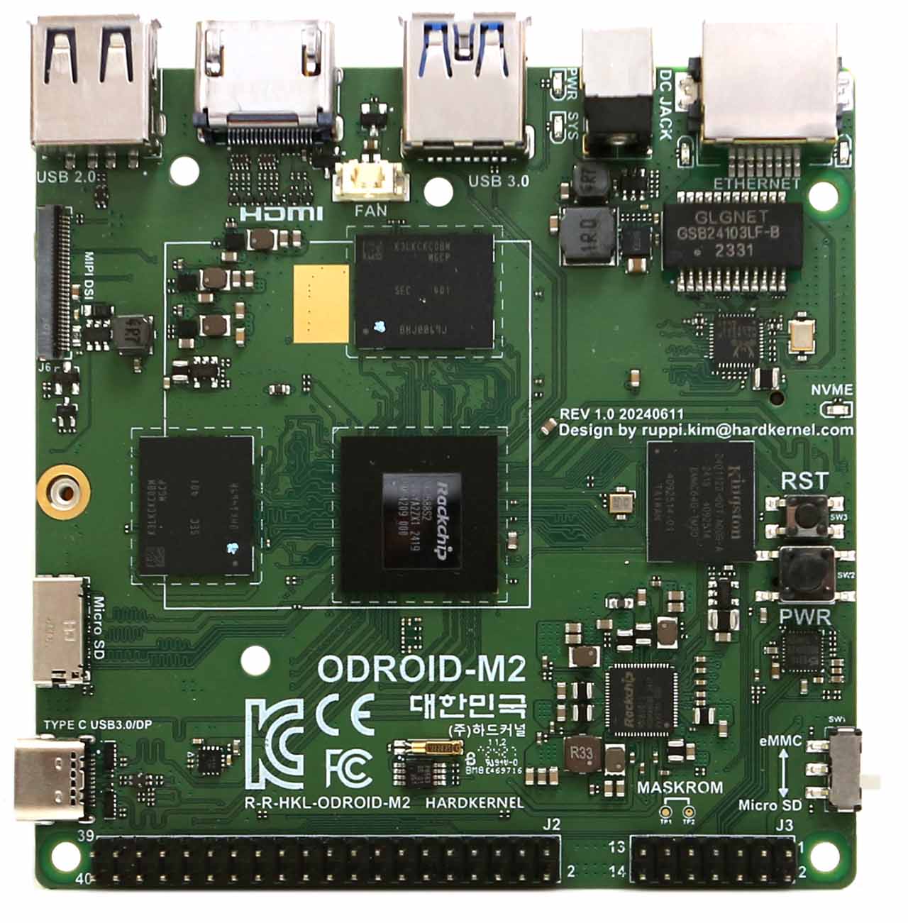
The M2 is a pretty neat little board that can run Ubuntu 25.04 smoothly, has an NPU for users who want it, and most of the Linux support code is already merged. It also has a 40-pin Raspberry Pi-like GPIO header as well as an extra 2x7 GPIO header with extra features. The SBC also features an HDMI port, USB-C with DisplayPort, a debug serial console port, MIPI DSI, and a gigabit Ethernet port.
The port
I started off by cloning the edk2-rk3588 repo and taking a look at the mainboard specific code. To make my job easier, I took the existing OrangePi 5 port and started modifying it for my purposes. These were the most important parts I needed to modify:
Voltage regulators
The first thing I would set were the voltage regulator parameters, as I figured these would be the most important for safe functioning of the board. Supplying wrong voltage to sensitive components can cause irreversible damage, so this is usually what I look at first.
This is the voltage setting code in the OrangePI 5 board code:
|
|
Let’s take a look at Odroid M2’s
devicetree
and grep for nldo to see if we can find the corresponding settings for our
platform:
|
|
According to this snippet, the NLDO1 regulator is powering the vdd_0v75_s3 plane, and the voltage is 0.75V.
Repeat this for every voltage regulator in the devicetree and we get this:
|
|
PCI Express Initialization
Here’s OrangePi’s PCIe initialization code:
|
|
From this we can gather a couple of things:
- There is a M.2 slot on the board
- There is no Power Enable signal for PCIe on this board
- There is a PCIe Reset signal, connected to GPIO_PIN_PD1 on GPIO controller 3
We need to understand how all this relates to the Odroid M2 we’re working with. Thankfully, Hardkernel provides us with schematics for this board: link
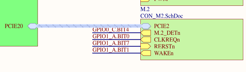
Here, we can tell that there is a reset signal on GPIO1_PA7.
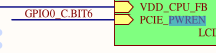
From this fragment we can tell that the PCIe power enable signal corresponds to pin GPIO0_PC6.
To summarize, we can see that on this board:
- There is an M.2 slot on the board
- There is a Power Enable signal, connected to GPIO_PIN_PC6 on GPIO controller 0
- There is a PCIe reset signal, connected to GPIO_PIN_PA7 on GPIO controller 1
So the code for our board should look like this:
|
|
Fan control
The Odroid has a small fan installed on the CPU heatsink that helps remove excess heat from the SoC. We should configure it properly to ensure the processor doesn’t overheat.
Let’s take a look at the schematic to see how the fan is connected:
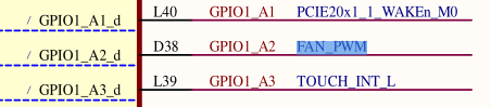
The PWM signal that controls fan speed is connected to pin GPIO1_PA2, which should be configured in PWM0_M2 alternate mode. PWM0_M2 corresponds to PWM controller 0, channel 0. Because the fan is small and has a small rotational mass, I had to set a low PWM period and duty (50 microseconds). This helps ensure that the fan doesn’t make a lot of noise at lower PWM duty cycles.
Here’s the code snippet.
|
|
Building
To build the board, simply execute the build.sh script from the root of the edk2-rk3588 repo:
|
|
This produces a binary that we can flash to hardware:
|
|
Flashing
The Odroid can boot from microSD cards, so let’s write the image to a card:
|
|
Now, let’s insert the card into the SBC and power it on.
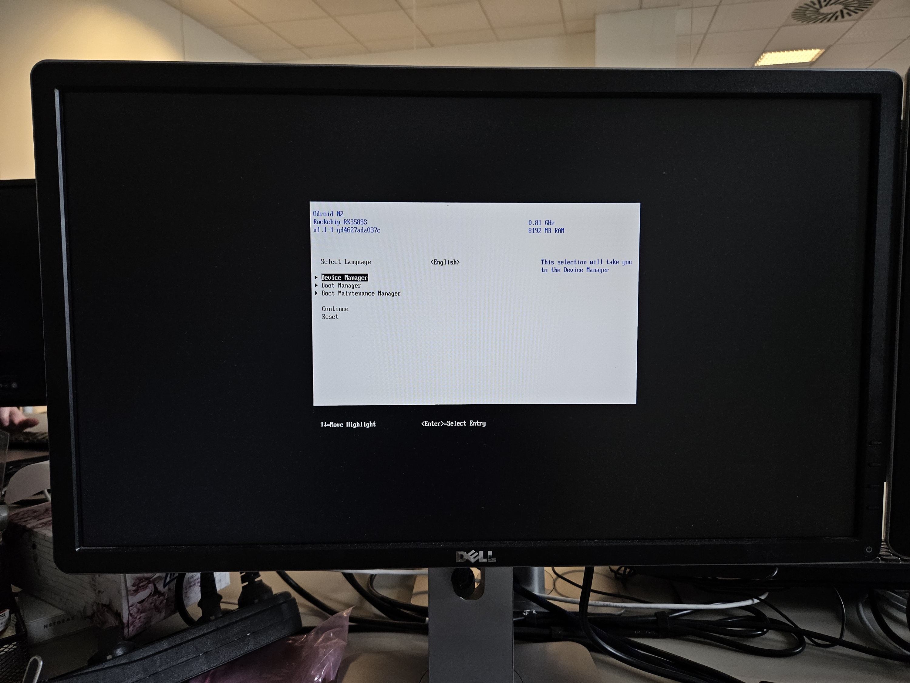
Success!
Summary
While the port is still incomplete and many things aren’t working as expected yet (booting Windows, USB3 storage in firmware, LEDs etc), the port is already capable of installing and booting Ubuntu 25.04 with most things just working. We are still far from a fully-fledged Dasharo release for an ARM-based platform, but this experiment gives us some experience and brings us that much closer to supporting this architecture.
The pull request to edk2-rk3588 adding the Odroid M2 port is available here.
Huge thanks to the edk2-porting people for maintaining the edk2-rk3588 repository and providing a solid base to build on. Check out their repository: link.
Dasharo User Group Community Call (DUG) & Developers vPub on September 18th at 4 PM UTC! During the call, you’ll have the opportunity to hear more about this adventure, as well as connect with Dasharo community members, ask questions, and provide feedback on our current activities.