Introduction
Remote work is trending nowadays. The best example is the IT industry - purely software tasks with handheld devices allow you to work practically from anywhere. This approach saves a big amount of time and makes a job easier. Unfortunately, as an embedded / firmware developer, there are often situations when interaction with hardware such as a power cycle is required. This leads to a barrier for successful remote work. Therefore, there is a possibility of connecting the target platform to the Remote Testing Environment product giving ready to go full validation set. In this blog post, I will explain the required steps to connect our device under test with RTE and then show the possible use cases for the whole setup.
RTE connection
Remote Test Environment has many interfaces available for the user. In this example, we are enabling RTE with APU2 setup for future validation, so we should focus on SPI, RS232 and GPIO interfaces.
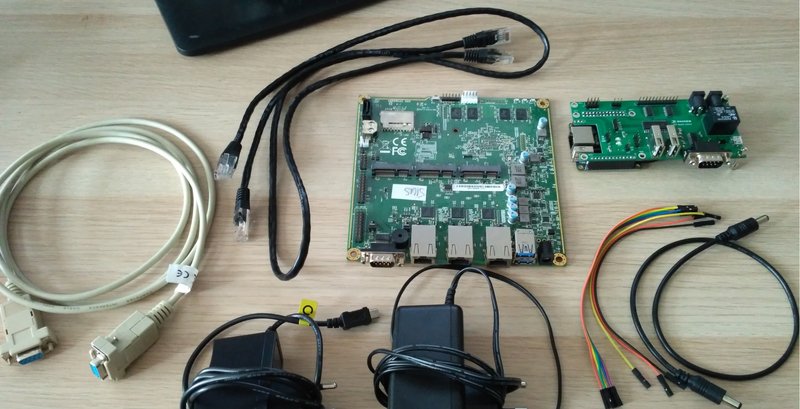
Our setup requires:
- RTE HAT,
- Orange Pi Zero with compatible OS installed on microSD card,
make sure that chosen system has devicetree modificated specially for OrangePi, e.g. Armbian or Yocto OS
- APU2 computer platform,
- 5V/2A micro USB power supply for RTE,
- 12V/2A DC 5.5/2.5 mm power supply for APU2,
- 1 x DC Jack to DC Jack 5.5/2.5 mm,
- 2 x Ethernet cable,
- RS232 null modem cable or 3(5) connection wires depending on the chosen option,
- IDC 2x4 pin cable or 5 connection wires for SPI.
Preparations
Plug microSD card to Orange Pi Zero slot and then connect RTE HAT with OPi header.
Network
Connect Ethernet cables to RJ45 connectors on Orange Pi Zero and APU2 platforms.
SPI
To setup communication between RTE and APU2 via SPI, connect J7 RTE header with J6 APU2 header using 5 standard female to female connection wires as described below:
| RTE header J7 pin | APU2 header J6 pin |
|---|---|
| 1 (NC) | Not connected |
| 2 (GND) | 2 (GND) |
| 3 (CS) | 3 (SPICS#) |
| 4 (SCLK) | 4 (SPICLK) |
| 5 (MISO) | 5 (SPIDI) |
| 6 (MOSI) | 6 (SPIDO) |
| 7 (NC) | Not connected |
| 8 (NC) | Not connected |
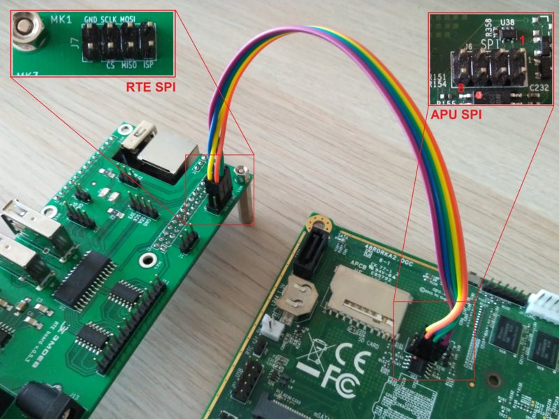
Alternatively, SPI connection can be realized with IDC 8 pin wire, but 7th and 8th wires have to be opened.
Serial
Serial connection can be established by RS232 D-Sub - D-Sub null modem cable. Connect RTE J14 DB9 connector with APU2. In case if you don’t have this kind of equipment, short RS232 connector pins in the following way:
Without hardware flow control:
| RTE RS 232 connector (J14) | APU2 RS 232 connector (J19) |
|---|---|
| 2 (RS232 RX) | 3 (RS232 TX) |
| 3 (RS232 TX) | 2 (RS232 RX) |
| 5 (GND) | 5 (GND) |
With hardware flow control:
| RTE RS 232 connector (J14) | APU2 RS 232 connector (J19) |
|---|---|
| 2 (RS232 RX) | 3 (RS232 TX) |
| 3 (RS232 TX) | 2 (RS232 RX) |
| 5 (GND) | 5 (GND) |
| 7 (RS232 RTS) | 8 (RS232 CTS) |
| 8 (RS232 CTS) | 7 (RS232 RTS) |
Other connections
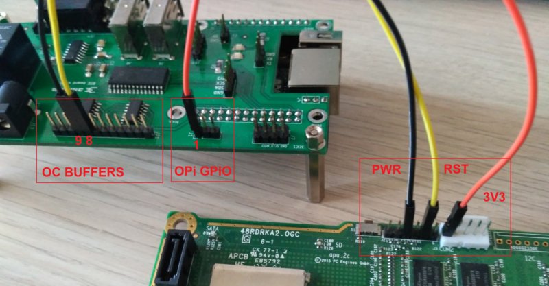
These connections are required for controlling APU2 power and reset states:
| RTE header J1 pin | APU2 header J3 pin |
|---|---|
| 1 (Orange Pi GPIO) | 1 (3V3) |
| RTE header J11 pin | APU2 header J2 pin |
|---|---|
| 8 (OC buffer output) | 3 (PWR) |
| 9 (OC buffer output) | 5 (RST) |
Power supply
Finally, it is time to power our platforms. Connect the 5V/2A power supply to RTE J17 connector or directly to Orange Pi Zero. Then connect the 12V/2A power supply to RTE J13 connector and RTE J12 to APU2 J21 connector via DC Jack to DC Jack cable.
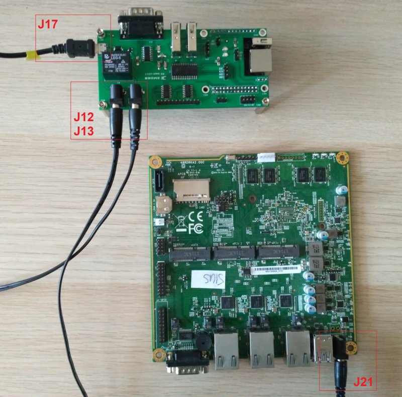
Full setup with all required connections is shown below:
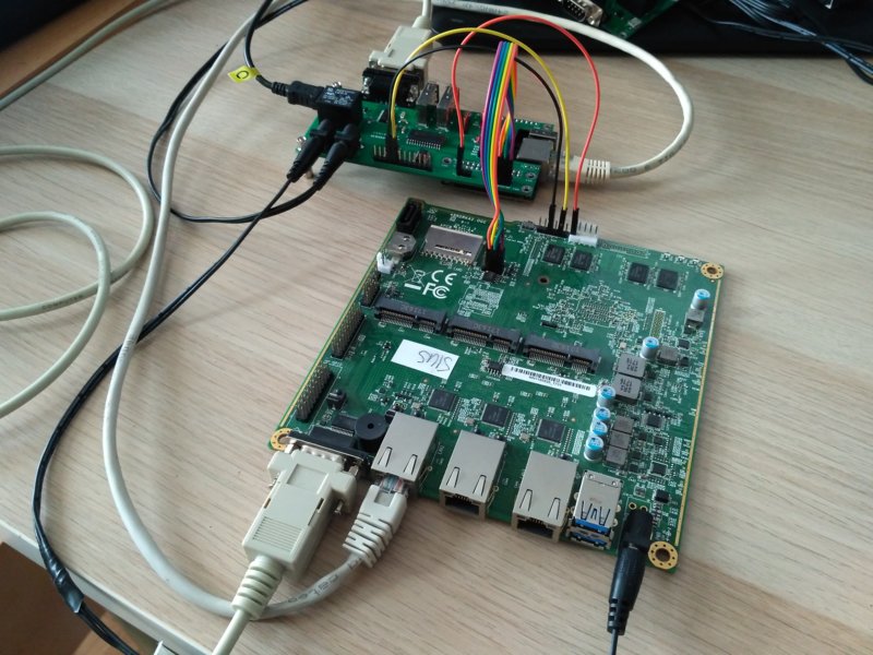
Theory of Operation
Remote work assumes an active network connection, therefore the IP address of
the RTE device should be checked beforehand. By default it’s configured by DHCP,
but I’m using RTE with static IP set to 192.168.3.105. To establish a
connection, type:
|
|
and login as root user - in this example I’m suggesting to use Armbian OS, but another viable choice is Yocto RTE meta layer. Next open telnet connection to enable APU2 console preview. Check if ser2net redirection is configured:
|
|
Open a new terminal or use tmux for split screen view and type:
|
|
we are using DB9 connector which is mapped to
/dev/ttyS1
Now, we have the ability to control Device Under Test from our personal computer and watch APU2 console on another tab.
To test, if our connections are correct, we can go through a firmware flashing procedure. I will use mainline release v4.8.0.2 from PC Engines github site. Generally, it’s an easy task. First, power on DUT by typing:
|
|
Save the APU2 console boot log for firmware version validation. In my example it is:
|
|
Send target firmware image via ssh, e.g.
|
|
Run commands manually or create a shell script:
|
|
Example flashrom output after flash verification:
|
|
New APU2 console boot log:
|
|
You can see that platform BIOS changed from v4.8.0.1 to the newer version
v4.8.0.2, which confirms that flashing with RTE was successful.
Summary
Above example is just one of multiple use cases that’s available for RTE users. Our HAT has SPI, I2C, extended gpio and OC buffers headers, relay with power control capabilities, DB9 connector and 2 additional USB ports, all ready for personal use.
In the near future, we will be releasing a new revision of Remote Testing Environment - brand new RTE HAT for Raspberry Pi Zero W. There will be a blog post about changes and functionality with the mentioned platform and section for validation setup where RTE with OPi will be testing its newer version. Stay tuned and feel free to share your awesome projects with RTE in the comment section below!
For more information about RTE, please check 3mdeb/RTE website, where you can order our new product in 3 different sets.
