Introduction
Geofencing1 is a mechanism that limits users' ability to perform certain actions or have access to any kind of resources outside of a specific area. The simplest example of geofencing is streaming platforms limiting access to certain shows available in other countries. …or a recent example from my life, I could not access the in-app ticketing system until I physically entered the Department of Transport building. While we often associate geofencing negatively, with “those greedy corporations restricting access for common folk” (I’m joking), the technology can also be used to increase security.
The problem is, however, that the geofencing often, but not only, relies on GPS or cellular information to learn the users' location. There are multiple problems with it:
- Devices like stationary computers or laptops often lack the needed hardware to access such information.
- The reliability is questionable as the list of data sources is too limited to ensure robustness.
- The information, like GPS location, can be easily spoofed.
- On devices that lack the necessary hardware, geofencing is often compromised already. Referring to the streaming services example, a mainstream VPN is often all it takes to access the restricted content (although it’s a fair point that these restrictions aren’t necessarily for security reasons).
But what if there existed a better way of verifying if the target user or a device is in the expected location? What if it was more reliable and would not require additional hardware?
In this blog, I’ll discuss the following:
- The theory behind Context-Based Authentication.
- Our involvement in the CROSSCON project.
- Describe the demo we prepared for the CBA.
CBA (Context-Based Authentication) theory
The CBA (Context-Based Authentication)2 generally relies on learning and assessing various types of patterns and detecting anomalies. Classically, the term is often used regarding user authentication. The factors like: user log-in time, the device the user is logging with, and sudden location change are being used as factors to successfully authenticate the user. In this blog post, I’ll focus on a different kind of authentication, that is, device-to-device authentication.
The main idea behind CBA implementation I’ll be describing is that each physical environment has a unique fingerprint (context). Similarly, how the friction ridges on the fingertip make a fingerprint, the digital fingerprint is a combination of the signal characteristics of the nearby transmitters and the physical layout that affects how the radio waves propagate.
The core assumption behind CBA is that no manufacturing process is perfect, and during manufacturing, some fluctuations happen that have a direct impact on the characteristics of the emitted radio signal. It should be noted that these fluctuations are within specification, so the communication is not affected by them, yet they are so unique that they can be used to identify a certain device. This characteristic is called Radio Frequency Fingerprinting3.
The receiver (a sniffing device) extracts these variations in the form of Channel State Information (CSI) provided by the Wi-Fi chip during frame reception. The CSI data describes the physical signal property; it not only reflects the transmitter hardware characteristic, but also environmental effects like reflections or scattering. All that information creates a distinct fingerprint (or context) that identifies the device’s environment4.
How “true” is the context?
I personally could not comprehend two questions regarding CBA:
- Why common identifiers like MAC addresses are not part of the fingerprint?
- Doesn’t the “resolution” of the received information take a huge role in the level of detail of the captured information?
The answer to the first question is quite obvious. The identifiers, like MAC or IPs, are easy to spoof. While in the context of huge datacenters, an operation like that might be hard to perform, it is a valid threat for less dense environments. Another fact is that classic networking, meaning digital processing, is computation-heavy as it relies on cryptographic operations, which is a concern often constrained IoT devices. The environmental data in the form of physical electromagnetic signals is both harder to replicate (spoof) and requires less computational overhead, as it does not need to be processed “on-board”.
For the second question, the resolution, consistency, and robustness of the captured data take a huge role. The low-end receiver’s capabilities to capture subtle differences are not as good as those of high-end devices. Moreover, the hardware can age, and the results will drift over time. While the machine learning algorithms don’t compensate for low-resolution output, they can “learn” the distinct features within the CSI data that remain discriminative across different devices.
Particular CBA implementation
Note: below, I’ll be describing the particular implementation that we received. The main person behind the implementation is Fabian Schmitt. The implementation is at the proof-of-concept stage.
The Context-Based Authentication implementation we received uses the onboard Wi-Fi chip to gather CSI (Channel State Information) of the nearby devices, just as described earlier. The host device used as a reference platform is the Raspberry Pi 4. The onboard WiFi chip takes the role of a sniffer in an attempt to capture various transmissions that happen over the channel, .eg, beacon and probe frames. The output of this process is a set of CSI information, information about physical channel properties. All the information the device manages to gather is what is referred to as a fingerprint or a context. The fingerprint will be slightly different each time the probing is performed, and that is to be expected. This is because the devices can change location, or the signals themselves might get distorted. The authentication scheme assumes there is another entity, an authority that assesses the match rate (similarity) between enrollment and verification. If the fingerprint created during assessment has a sufficient match rate, then the authority grants the signature to the assessing node. That signature can later be used to authenticate to yet another service.
To help better visualize this architecture, I created the following diagram.
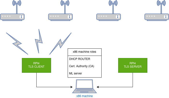
The above diagram showcases the setup I used for ad-hoc testing. The x86 machine (my work laptop) takes the role of a DHCP router, CA, and hosts the Machine Learning Server. The Machine Language server is the authority that grants the signature to the client, which it uses to authenticate to the server. This will be elaborated on in the “UC1-2 overview” and “setup” sections. It should be emphasized that, under normal conditions, the routing would be handled by dedicated networking gear, and the nodes would be just a part of a distributed network, instead of being directly connected.
Learn more about CBA
What I managed to touch upon is only the tip of the iceberg when it comes to CBA. The main source for the knowledge I was using as reference was CROSSCON the D3.3 document5, especially 3.3.2 section. If you want to learn more about the concept of CBA, this is the right document.
CROSSCON and the fascinating stack behind it
Brief introduction… CROSSCON stands for Cross-platform Open Security Stack for Connected Devices6. We are partnering with other companies and research centers to innovate on security technologies for IoT and connected devices. The main product of the project is the CROSSCON Hypervisor, a lightweight hypervisor that provides a unified way of running virtual machines on hardware powered by MCUs as well as on embedded computers like Raspberry Pi 7. Currently, it is at TRL 3-4. Take a look at this example…
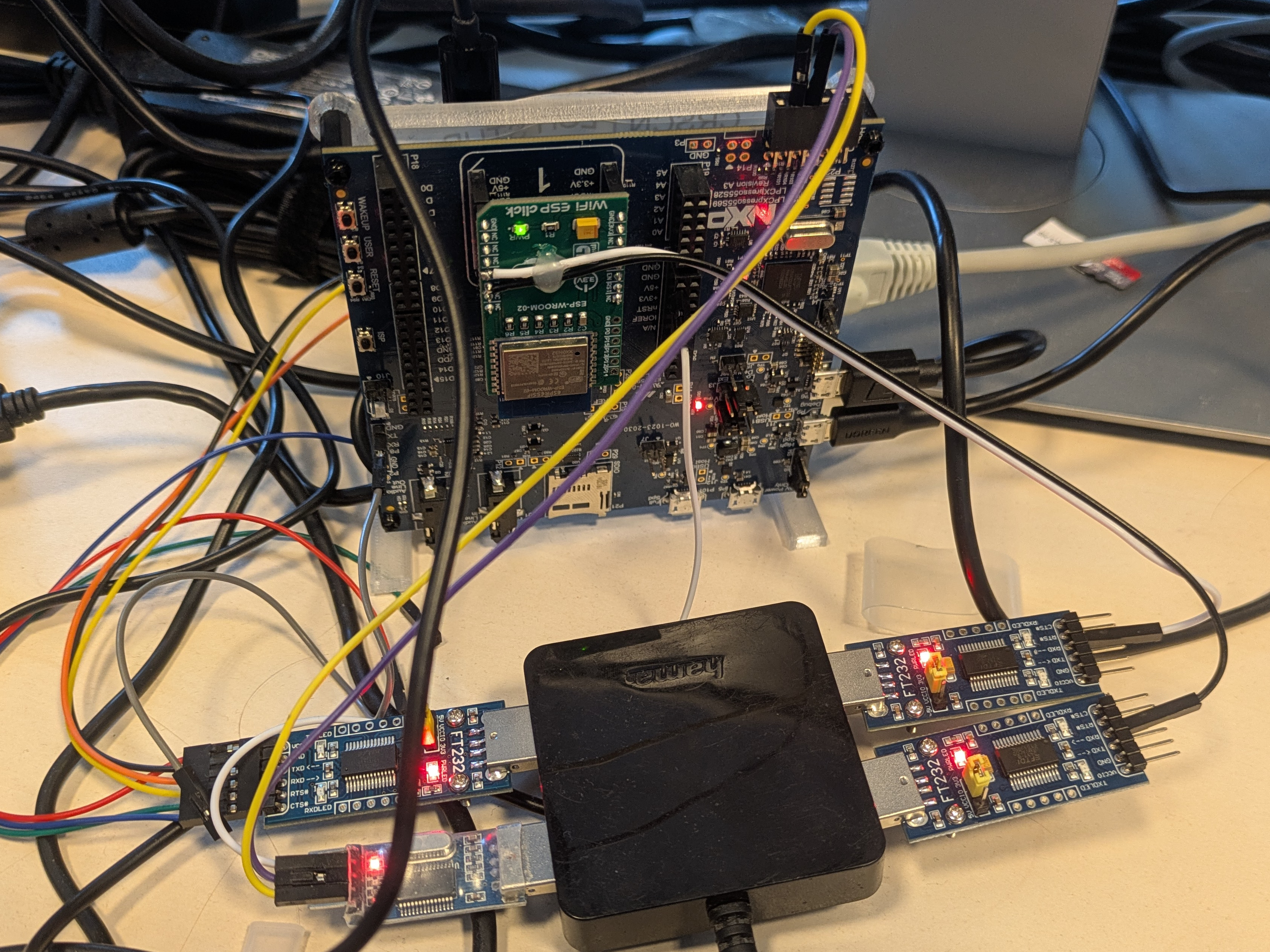
The picture showcases LPC55S698, an MCU-based platform with a bunch of UART adapters connected. It was my “on-desk” development setup for debugging a PUF-based authentication implementation.
Interestingly, the chip is quite popular in the world of hardware security. It has been showcased how undocumented hardware can lead to subvert expected boot and API behavior, therefore compromising the hardware root of trust9. Thanks to that, the platform has been hardened even more. It is used as a part of the Nitrokey 310 from the company Nitrokey, with which we collaborated. But I’m going too far off topic…
In the demo we refer to as UC1-1, two VMs were running on said LPC55S69 platform: a TEE (Trusted Execution Environment11) VM providing access to the hardware PUF controller, and a REE (Rich Execution Environment) TLS client application that could communicate with the second VM to authenticate on a foreign host.
Correct, two VMs running on a freakin microcontroller… How cool is that?
Note: Needed an excuse to showcase this cool picture I took. Sorry, not sorry… 🤷
This isn’t our first post on the CROSSCON project. If that interests you, you can check out this12 and that13 post.
Custom CBA Implementation
As stated earlier, we were given the basic implementation for the CBA service, and our task was to use it in a particular use case. The use case I’ll be describing is referred to as UC1-2.
UC1-2 overview
The UC1-2 demo is a simple mutual TLS14 server and client messaging application. The aim of the use case was to showcase that the devices can be authenticated by the contextual information. The flow is simple; there are two RPI 4 platforms connected via a common network. One of the nodes performs the role of TLS server, while the other is assigned the TLS client role. As the first factor, both nodes perform a mutual TLS handshake and open up a TCP socket connection over TLS. Once the connection is opened, the client needs to prove the environment it’s in (if it has proper context) to the server. To do so, a mechanism described in the “CBA theory” section takes place. The client requests verification from the independent authority (yet another machine), and if the context information it provides has a sufficient match rate, it is granted the signature it uses as a prove for the server. If everything succeeds, both nodes exchange a message, and the execution stops. Simple right?
The architecture
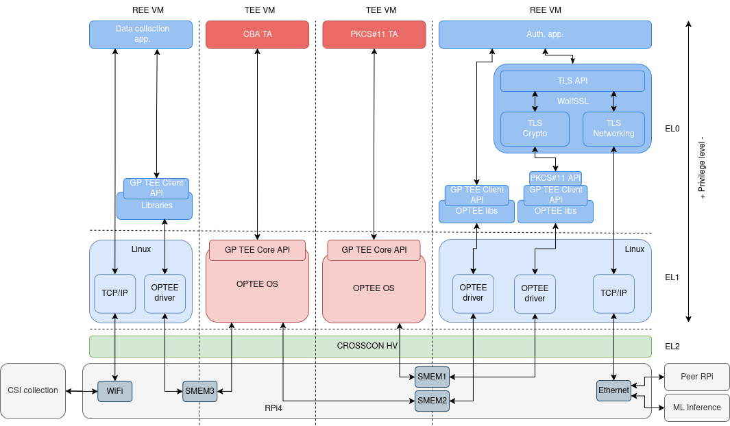
Now let’s take a look at the stack that’s running on a single Pi.
Not so simple anymore, huh?
As showcased in the picture above, a single Pi runs a total of 4 VMs. Starting from the right side, there’s the main REE running a custom, buildroot15 based Linux distribution. This Linux distribution is a host for the TLS client or server application, depending on which node takes one of the roles. The CROSSCON hypervisor the whole stack is being managed by, allows creating data exchange channels between the VMs, known as “shared memory”. It is a common, reserved space in RAM memory where the VMs can exchange information.
One of the said VMs is PCS#11 TA running on top of OPTEE OS under TEE. This Virtual Machine performs the role of a secure vault for the private keys that the nodes are using for the first factor TLS authentication.
The next VM to the left is the one I’ll be referring to as the CBA VM. Just as the one previously described, the VM consists of OPTEE OS and the “CBA TA” running on top of it. It also uses a standardized API to communicate with the main Linux VM I already described. CBA TA serves as a trusted service that handles capturing CSI information. There are two networking interfaces on the RPI 4 platform: Ethernet controller and Wi-Fi. The TA communicates with the machine learning server using the networking stack of the REE Linux VM, over Ethernet.
The Wi-Fi chip is handled by yet another Linux-based REE (the VM furthest to the left on the diagram). The issue is that the WiFi chip on the RPI4 platform does not disclose CSI information; thus, a special driver and firmware are needed. There were issues with implementing the driver under OPTEE OS; thus, the decision was made to utilize the networking stack of REE Linux VM.
Note: The described VM stack being identical for both nodes, only the TLS client node utilizes VMs responsible for CSI data collection.
What isn’t showcased on the diagram is a machine learning server that grants the signature to the client, as well as the CA that signs the certificates for both nodes. This was showcased in the “Particular CBA implementation” section.
The setup
To prove the solution is working as expected, I had to get creative and make my development setup mobile. Well, here it is…
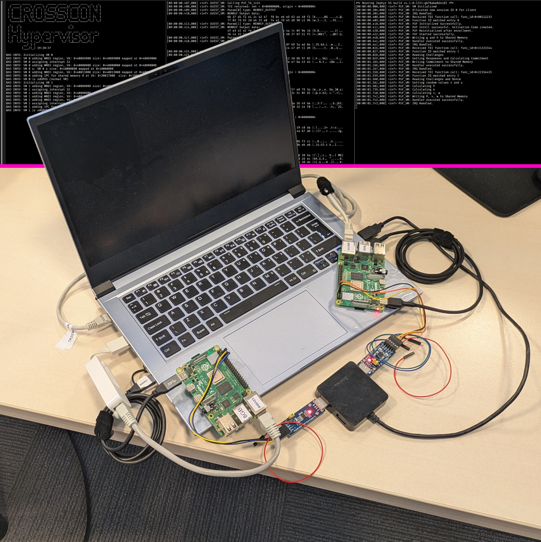
Just take a look at that beaut! Where do I start…
What you’re seeing is my work laptop and two RPI 4 platforms. Both RPIs run the stack I described in the previous paragraph. The architecture follows the diagram showcased in the This was showcased in the “Particular CBA implementation” section. The laptop is serving as: a router, CA, machine learning server, and a power source for two RPIs. You can see the Pis are connected via Ethernet cables, as the Wi-Fi chips are used for gathering CSI information. Additionally, you can see two UART adapters connected to both PIs. These are initially needed to kickstart the hypervisor and configure networking. Once the networking is configured, I can communicate with the platforms over the SSH protocol.
Testing
To test if the use case is working as expected, I had to slightly modify the TLS server/client application to do a total of 3 verifications and take the result of the final one for the verification. The reason was, I had to sanity test that during the single execution, when the platform context changes, the client is granted or denied access from the authority. The scenario I executed was as follows:
- Enrolled the TLS client platform in a base environment (the office space).
- Allowed the demo to proceed to the first verification has been done. The verification succeeded as expected.
- Moved the whole setup to the remote location so the devices could no longer access the devices in the base area. The point of reference was losing Wi-Fi connection on the laptop. The remote area was the office kitchen, on the other side of the building.
- Allowed the stack to proceed with the second verification. The verification failed as expected.
- Moved back to the base area and allowed the third verification to proceed. The verification succeeded, and nodes exchanged messages as expected.

I wonder what other people in the kitchen thought seeing me carry this contraption…
Readiness
I have repeated this test multiple times by now, and I can say that 90% of the time it works as expected. I believe it happened once that client verification succeeded in the remote area, and once the client could not be authorized in the base area. As stated many times earlier, the whole stack is very complex, and it is in the proof-of-concept stage. It showcases what is possible, but it’s too early for integration.
Summary
I discussed the base concept behind the CBA and showcased an implementation example. I hope I also proved why Context-Based Authentication is superior to geolocking and its potential in being a security mechanism. While the UC1-1 is very simple and does not showcase the full potential of this technology, I can totally see it being used in various scenarios, like:
- ability to use the work computer only in the office (as theft prevention),
- erasing sensitive information if the device leaves its origin place,
- being able to access resources only in certain environments,
- and many more.
…and all of that without the need for any extra hardware modules.
If you want to learn more, in the section below, I have listed various resources that might be handy. The CROSCON project repositories are public and available to anyone. Remember, currently the demos are just a proof of concept. I’ll also be showcasing the demo of CBA during the upcoming Zarhus Developers Meetup. Feel free to join if you’re interested.
References
Events:
Additional resources:
- Crosscon hypervisor repository
- Build-system for UC1 demos for RPI platform
- TLS server/client application for RPI platforms
References list:
-
https://www.okta.com/identity-101/context-based-authentication/ ↩︎
-
https://crosscon.eu/sites/crosscon/files/public/content-files/2025-03/D3.1%20CROSSCON%20Open%20Security%20Stack%20Documentation%20%E2%80%90%20Draft_v1.0.pdf ↩︎
-
https://oxide.computer/blog/exploiting-undocumented-hardware-blocks-in-the-lpc55s69 ↩︎
-
https://en.wikipedia.org/wiki/Trusted_execution_environment ↩︎
-
https://blog.3mdeb.com/2025/2025-04-10-crosscon-its-hypervisor-and-zarhus/ ↩︎
-
https://blog.3mdeb.com/2025/2025-10-02-crosscon-hv-wifi-zephyr/ ↩︎
-
https://www.cloudflare.com/learning/access-management/what-is-mutual-tls/ ↩︎