ESP8266 is a SoC made by Espressif. For last couple of months this chip is a rockstar of HackADay and makers community around the Internet. Mostly because of WiFi modules built based on it (ESP-XX family). Rich interface (GPIO, SPI, SDIO, I2C) give those boards potential to be standalone MCU with WiFi capability for wide range of applications. In quantity you can get ESP-01 for $2.7 (for 1kpcs). Of course there is no free lunch. Documentation is weak (this is no TI), but community doing it’s best to change this state. Native interface of AT commands is also not the friendliest way of communicating by beginners. But also for that market found solution - namely NodeMCU.
A while ago I bought ESP-01 and experiment a little bit with it. I quickly realize that to release additional powers from this module I need access to other pins. ESP-01 expose only 2 GPIOs newer versions of the board provide more and more. Of course there was a way to hack ESP-01, but using latest version usually provide better feature set. Latest version known to wide public is ESP-12 which expose ADC and 9 GPIO pins. Finally I took in possession couple of them.
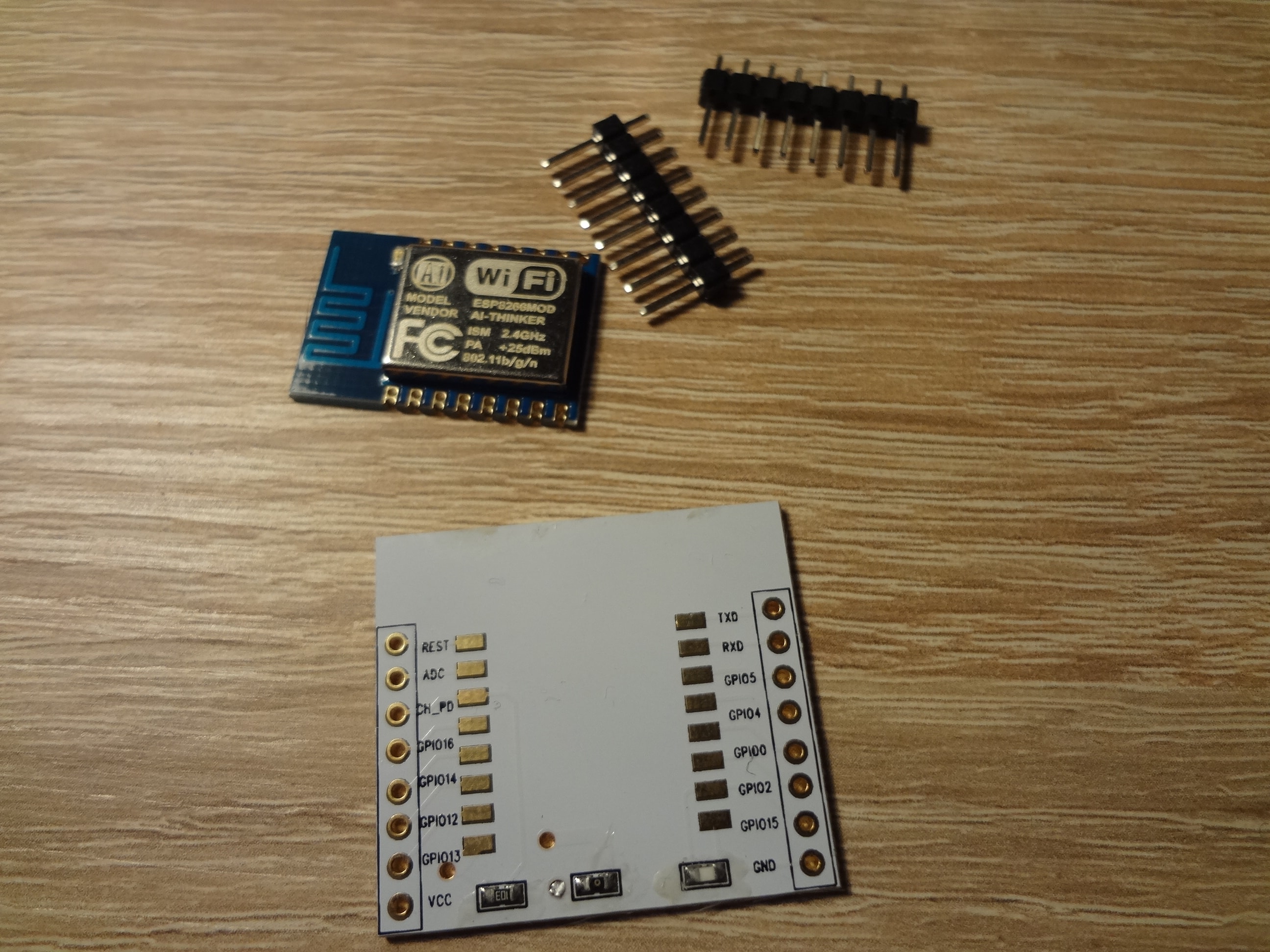
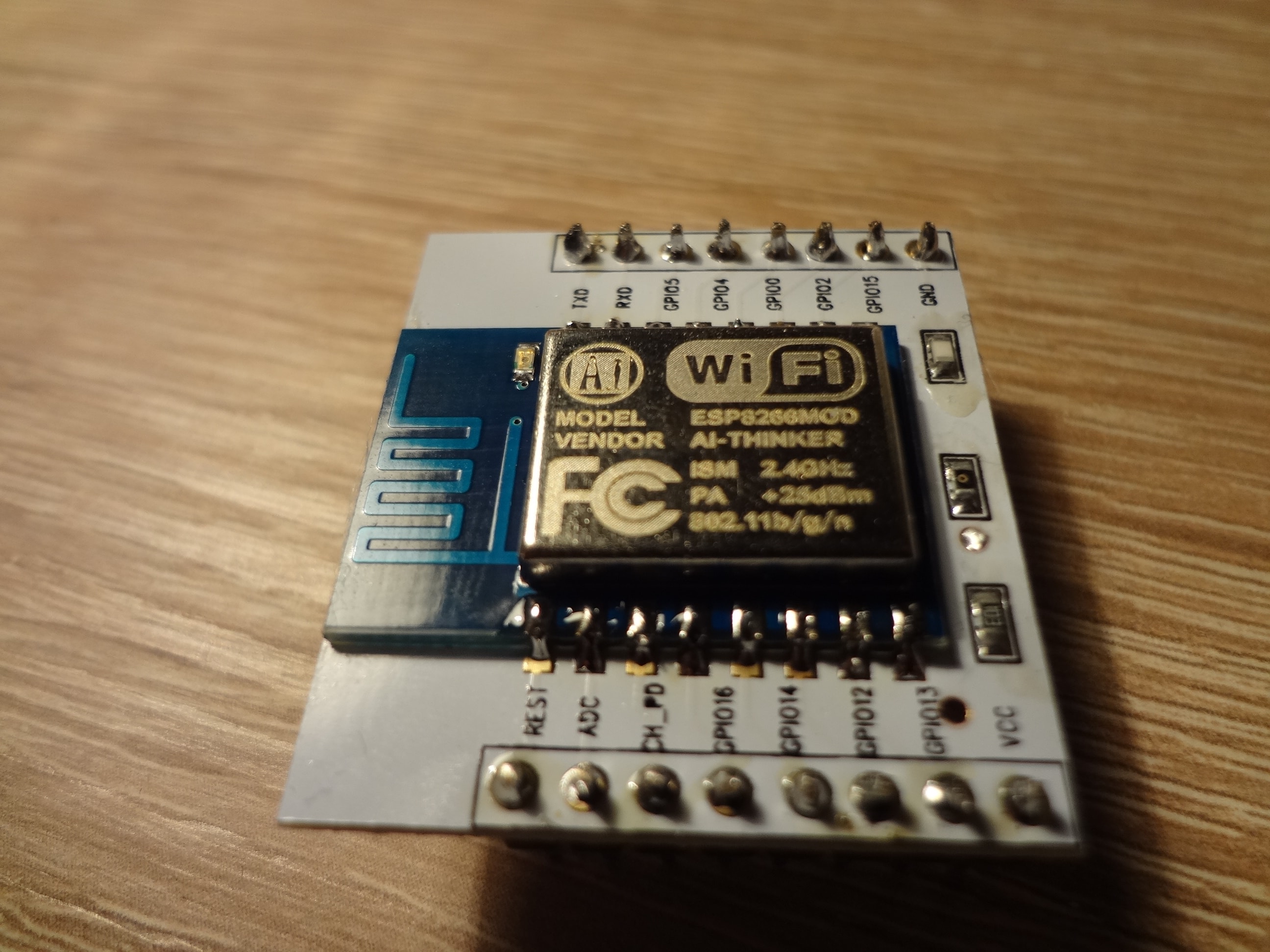
Soldering
Because this board came in SMD package I found that ElectroDragon provides also adapter to solder module and easily expose pins.
After applying my soldering-fu I get rewarding result.
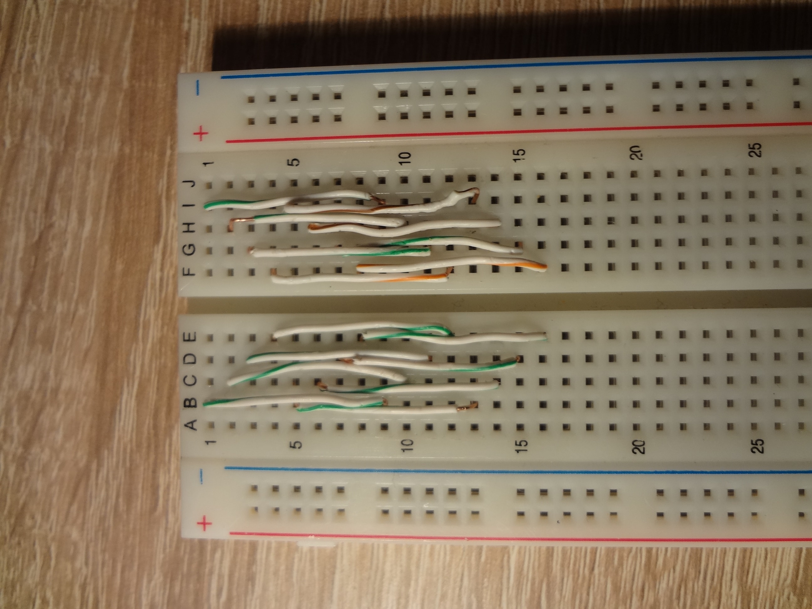
Wiring
ESP-12 adapter from ElectroDragon got width of 31mm and pin distance match ideally to prototype board. There is only one problem that adapter width put pins into first and last column of the standard 10 column (A-J) breadboard. Which give no ability to connect parallel wires, which was my initial idea. Because I didn’t have u shape solderless jumpers to make connection clean I split old Ethernet cable and get this:
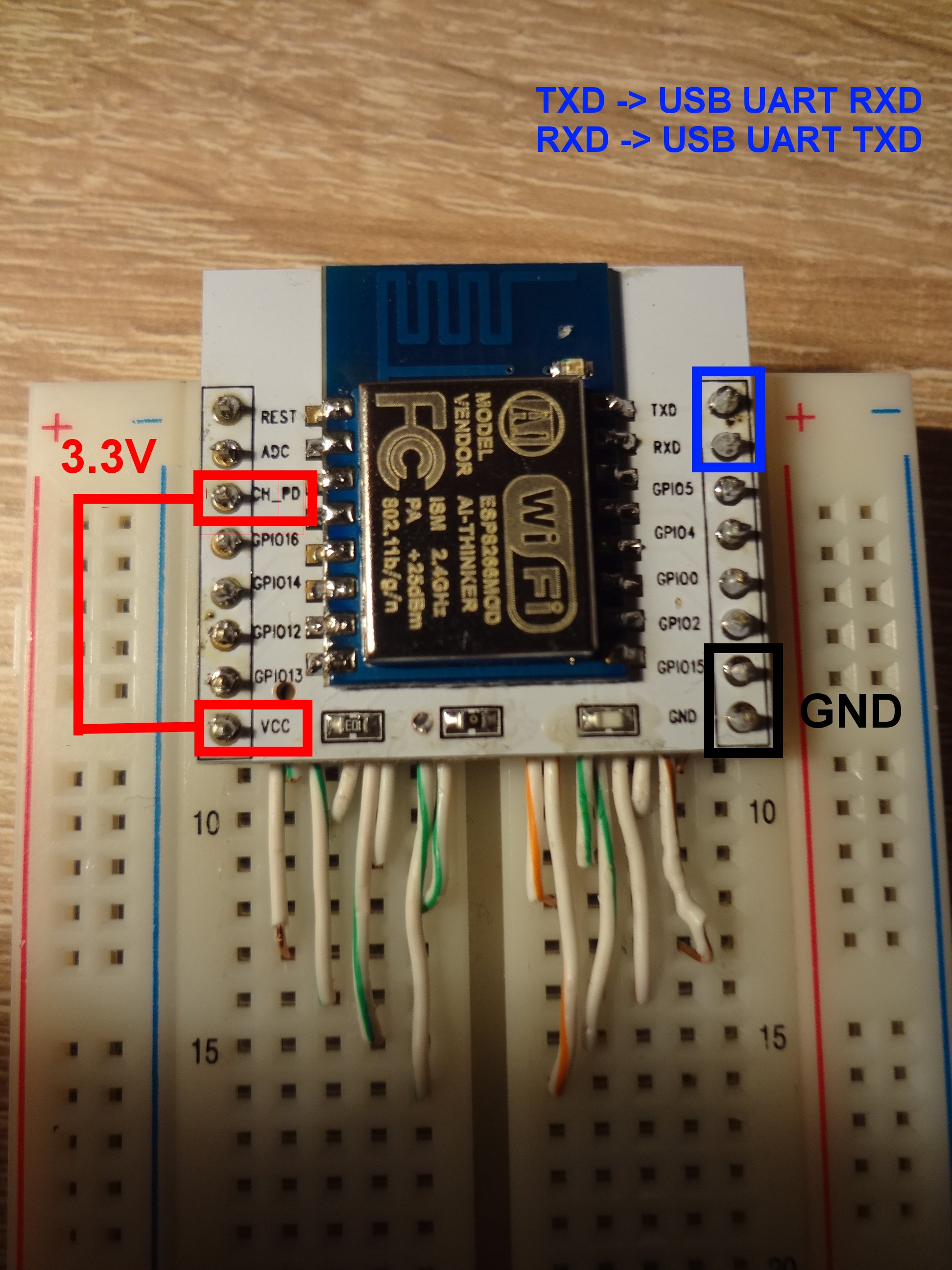
Check connections couple of time to make sure that everything works fine. As USB UART I used FT232RL based module. Current provided by USB UART module can be insufficient that’s why I used lab DC power supply.
NOTE: Both ESP-12 and USB UART should be connected to the same GND.
Power on
It wasn’t simple. First I tried minicom with 115200 UART speed:
|
|
This module display bootloader messages at 115200. After booting it switches to
9600. If you booted and can’t communicate but blue LED blinking when you type
this may indicate that you need reset try AT+RST<Ctrl-M><Ctrl-J>. You should
get something like this:
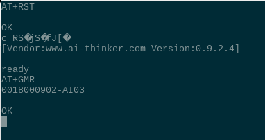
There are lot of other commands like AT+GMR which give you firmware version.
More commands you can find
here. Not
every firmware support all commands. To use more robust firmware you can compile
latest version of AT command or even modify it according to your needs. Some
instructions can be found here.
Summary
I think that ESP8266 has great potential to make pressure on market and squeeze better solutions. There is a lot of interesting things going on around ESP like MQTT implementation of firmware or recently released FreeRTOS SDK from Espressif. I hope to write more about ESP-12 in future. If you think this post was useful please leave a comment or share with friends.