Introduction
3mdeb Embedded Systems Consulting is a company that evangelizes open-source software on all levels. That includes the firmware, bootloaders, hypervisors, operating systems, and more. As befits a company promoting open-source, it should utilize open-source in daily lives. That is our hardware should run open and secure software whenever and wherever possible. Since the center of our daily work is a workstation, it should meet our requirements in the first place. Most of the employees' PCs in 3mdeb are either HP Compaq 8200 / 8300 (Elite) or Dell OptiPlex 7010 / 9010. Because our company is a licensed coreboot consultant, it would be a shame for us to not have our hardware running coreboot. While the HP workstations are supported in coreboot the Dell machines are not (or rather weren’t in 2018 when I started my work with them). This post will take you into my journey of porting the Dell OptiPlex 7010/9010 to coreboot. If you did not read the first part, I highly encourage you to do so here. So let’s start were we left last time.
Super I/O chips
In the previous post I mentioned that one day a power cut occurred and the machine lost the AC power. When I tried to power the platform on, it was no longer booting. I kept wondering what has gone wrong. Of course there are lots of power management related registers out there in the main processor which could ruin my day when configured incorrectly. So I began looping through them in the datasheet and looking for issues in the coreboot code, however I could only come up with this patch A minor fix that addresses differences between mobile an desktop platforms which in final result did not resolve my problem. I had experience with the codebase used on the Dell OptiPlex 9010 already because it uses the same code a Lenovo Thinkpad laptops, especially x220 which I flashed with coreboot long time ago and is working without issues. So the only thing that could break is the Super I/O chip.

Many of you probably have no idea what kind of chip is that. Super I/O is an integrated circuit which expands the I/O peripherals in the standard x86 PC system. Back in 80’s or 90’s floppy, PS/2, printer port, RS232 ports were quite common and popular in PC systems. However these peripherals became deprecated and called legacy. Super I/O are designed to expand the x86 system peripherals with such legacy devices and features. By default they are connected to the LPC interface (a modern version of ISA bus). Among others the TPM or the post card can be connected to LPC interface which can be exposed as a debug header to read the BIOS post codes. Back in the first part of the series I have told that the driver for the Super I/O chip has been developed for the SMSC SCH5545. At this point I had the serial port working along with the PS/2 keyboard and mouse. However the serial port stopped working whenever the machine lost the AC power. Noticing this small issue took me many days and on the first glance shouldn’t prevent the board from booting, right?? Well, the answer is: NO!
First of all, why it took me so many days to figure it out?
No matter how dumb it may sound like, but my builds were always with the onboard serial port enabled for debugging. Because why should I ever get rid of my main debugging method?? Of course there are other methods like USB debug dongle, but what for I have already a serial port… What is more I have verified it is working (at the beginning I had no idea it stops working after AC loss).
Secondly, I have interpreted the symptomes incorrectly
After the AC loss, the first thing I have noticed is that the led on the power button is not shining white. For clarification SCH5545 has a two-color LED driver that allows to change its colors based on the register initialization. Apparently the OptiPlex 9010 power button is equipped with an orange and white led. When the white led shines, it means the BIOS has started fetching and executing the code (which is good). However, if the registers are not configured correctly the power button was shining in orange color giving some error signal (the led was shining in intervals). My first conclusion was that the machine is not even starting after AC loss, because I had the code written for the leds to set them white and executed very early.
Another symptome was the fan which started to run on full speed after a few seconds after I pressed power button. I thought initially, no big deal, if the machine is not starting it does not probably retrieve temperature from CPU or something.
Summing up all those issues together I was almost certain it has something to do with the Super I/O and it prevents the board from booting. Of course the coreboot had not implemented all functionalities yet, but the bug was so severe that the board was not booting. I have looked into the datasheet of SCH5627 and noticed there is an Embedded Memory Interface (EMI) there which implements access to the Environmental Controller internal memory. “That must be it” I thought…
It is everything your fault
Typically Super I/O chips are not that complex in design and operation, however those from SMSC stand out very much. There is no standardized access to hardware monitoring registers like temperature, fan tachometers and PWM for fan control (unlike the chips from ITE for example). So basically the manufacturer left the door wide open to developers and let them design the Environmental Controller firmware to perform the hardware monitoring and implement any communication protocol they want through the EMI. That doesn’t sound good for me since I will have to go through reverse engineering path… Congratulations to Dell engineering team for well-designed and complex interface to the environmental controller. It gave me a worthy challenge.
Based on EU Directive 2009/24/EC Article 6 to achieve interoperability of the SCH5545 driver with coreboot I had to obtain necessary information by translating the vendor code from the firmware image. I had no other way to make these software components work together in the correct way. I did the reverse engineering because of interoperability issues with coreboot. It was done in my personal unpaid time for the benefit of community.
Reverse Engineering of the EC
Since I didn’t have almost any experience with reverse engineering before and additionally I was not in favor of UEFI, it was quite hard for me at the beginning to reverse EFI files. Finding the best working environment is the first and foremost step to begin the reverse engineering. There are a few notable frameworks to work with: radare2, Ghidra, IDA and Binary Ninja.
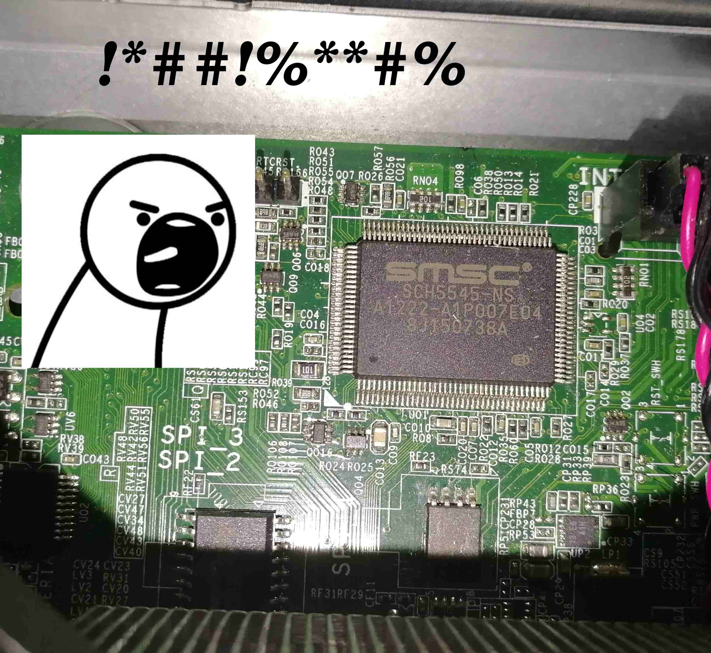
 Source: https://twitter.com/securelyfitz/status/1143213013484232704/photo/1
I decided to give Ghidra a try since it is free and also has some good firmware utilities for EFI binaries that were developed by a student on GSoC. Note the tool was developed by NSA, so if you have any doubts when using it, consider other tools or Qubes OS disposable VM for isolation.
The Ghidra firmware utilities are very good to start with, since they parse the PE header, look for known GUIDs etc. Additionally it provides EDK2 datatypes integration to name variables, structures and interfaces. For example:
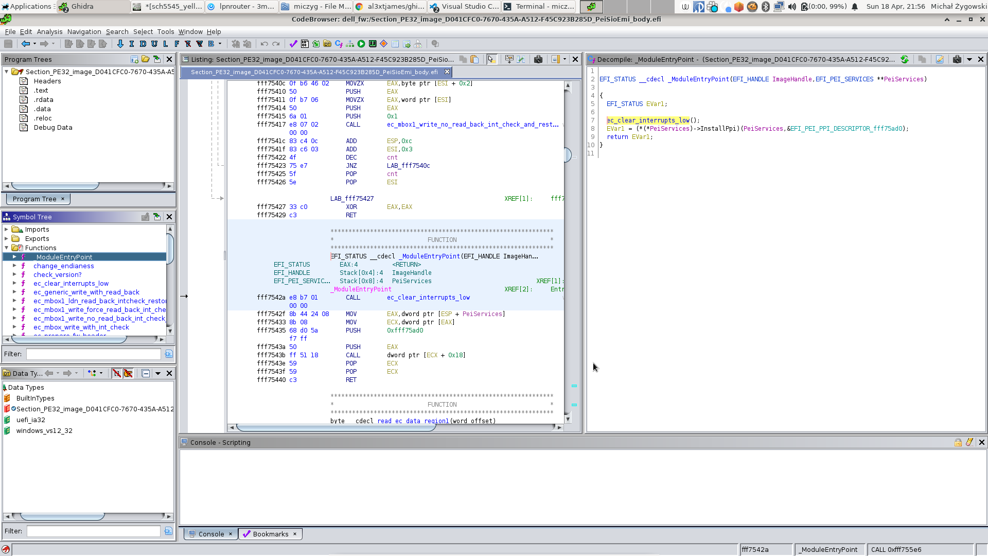
As you can see the window is divided into code listing and the decompiler. As you probably guessed already, the decompiler is our main weapon. Thanks to the integrated EDK2 datatypes from UEFI specification we already see the human-readable code:
|
|
There is also a script that translates some known structures and names
automatically. This helps a lot in obtaining some understandable code initially.
Note must be taken since the script translates the types from UEFI DXE modules
(which run from system RAM) and does not recognize PEI modules (which run from
SPI flash directly in cache). So for example I was making a stupid mistake and
reversing PEI modules with
_ModuleEntryPoint(EFI_HANDLE ImageHandle,EFI_SYSTEM_TABLE *SystemTable) which
is only true for DXE and UEFI executables. So it is not always good that a
script does something automatically for you.
Long story short I have been reversing those modules one by one which were related to the SCH5545 and EMI. I spent a lot of time on that and I still have got zero clues what to do next. This wasn’t however wasted time, because I had to do it sooner or later.
Final conclusion
Many days passed without any action on my side. Then, one morning I have been enlightened. “What if the board actually starts but does not give any signs of life?” and then… Yesss… After the AC loss the Environmental Controller might lost its configuration and that also means other functions may not work as well. Before the AC loss, I did not have to configure Environment Controller and fan control. The fan was working silently. However just after the AC was lost, the fan started to spin at full speed when the board was powered on. It is possible that the Environmental Controller keeps its configuration as long as standby power is supplied. So taking it into consideration and all my previous conclusions I have decided to enable the USB dongle debug instead of the onboard serial port. Why? Look at this (source):
|
|
So the UART driver in coreboot checks whether a character can be transmitted
over serial port and then transmits it. However, if the serial port is not
functioning, the while loop may be reaching the defined timeout, which can be
even up to 50ms. Now image: full debug coreboot output has over 50000
characters. So a quick calculation: 50000 * 50ms = 2500000 ms = 2500s ~ 42min.
So the whole boot process would take over 40 minutes, no wondering that I have
assumed that the board is not starting at all. This is the first time I have
encountered such issue with Super I/O where the serial port is not working
despite having a known good driver. Just in case I stopped producing builds with
onboard serial port as the main debug method. I bought FT232H which is supported
by coreboot and used it as EHCI USB debug dongle. I was able to get the debug
output from coreboot without worrying about AC loss or whatsoever.
Summary
So the issue with board not booting after AC loss has been resolved, or at least located. It took me enormous amount of time to figure it out. But don’t feel sorry, it’s a daily firmware developer job to debug for many hours just to find a simple fix. And I kind of like it. It is a professional deviation I could say.
In the next post I will disclose more details how I implemented the Environmental Controller driver for the Dell OptiPlex 9010. It should show some progress on making the fan control work and how I have achieved the current implementation level which is available in upstream coreboot repository. Also you will see how far one has to go to achieve a goal in firmware development. Stay tuned.
If you have a problem with the Environmental Controller (EC) of your platform,
looking to write EC debugging or updating utilities, we are one to discuss.
Also, since
EC firmware ecosystem shifts to Zephyr
and we are huge fans of Zephyr. We would be glad to implement Firmware or even
Open Source Firmware for your EC. If you are interested, feel free to
book a call with us or
drop us email to contact<at>3mdeb<dot>com. If you are interested in similar
content feel free to sign up for our newsletter