What is MuxPi?
MuxPi is a next open hardware device, after RTE shield, that serves for developers and testers with the need of automating everyday tasks. It comes with help providing ease of use, distribution and connectivity.
The name MuxPi comes from the connection of “SD-mux”, which is the previous
version of this project indicating one of the main features of the board and the
very popular SBC computers with the “Pi” suffix.
MuxPi consists of two main parts:
- Mainboard
- NanoPi NEO
It might be considered as some kind of mainboard for NanoPi NEO SBC but it can operate without NanoPi NEO. However, in such a scenario its functionality is heavily reduced.
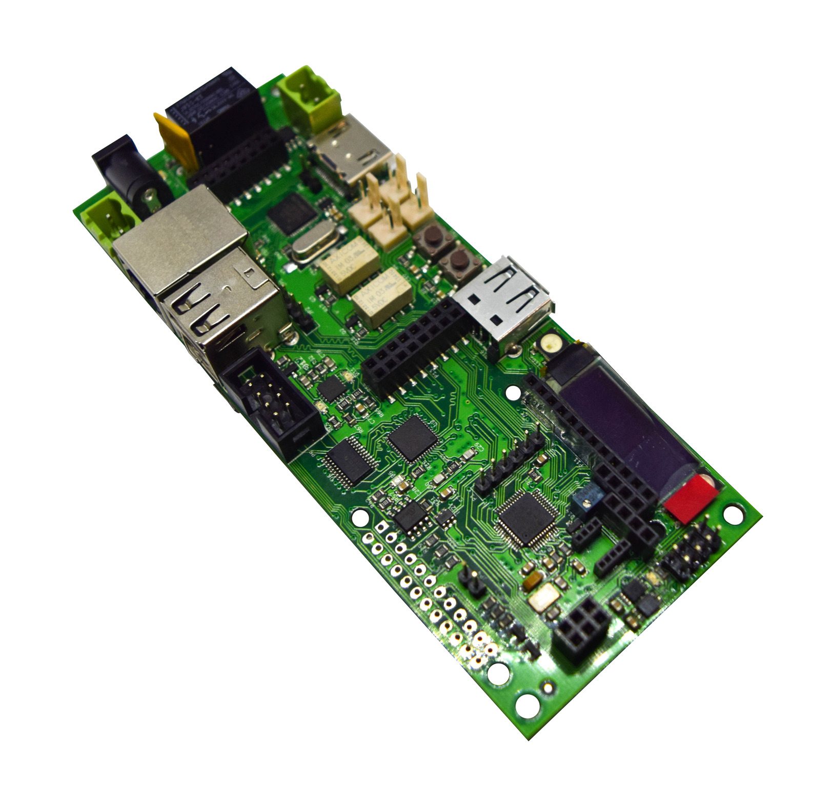
The primary purpose of the muxPi board is to enable fully remote work with devices being tested, where hardware setup can be separated from the developer. The main advantage of this board is a large number of various interfaces, making muxPi very versatile testing board.
Key features
Compatibility with NanoPi NEO
MuxPi is fully compatible with the budget (~13$) Single Board Computer platform called NanoPi NEO. It connects through three NanoPi headers, fully inheriting the capabilities of the little platform. From the moment of putting together the two elements, NanoPi becomes the “heart” of the muxPi validation kit.
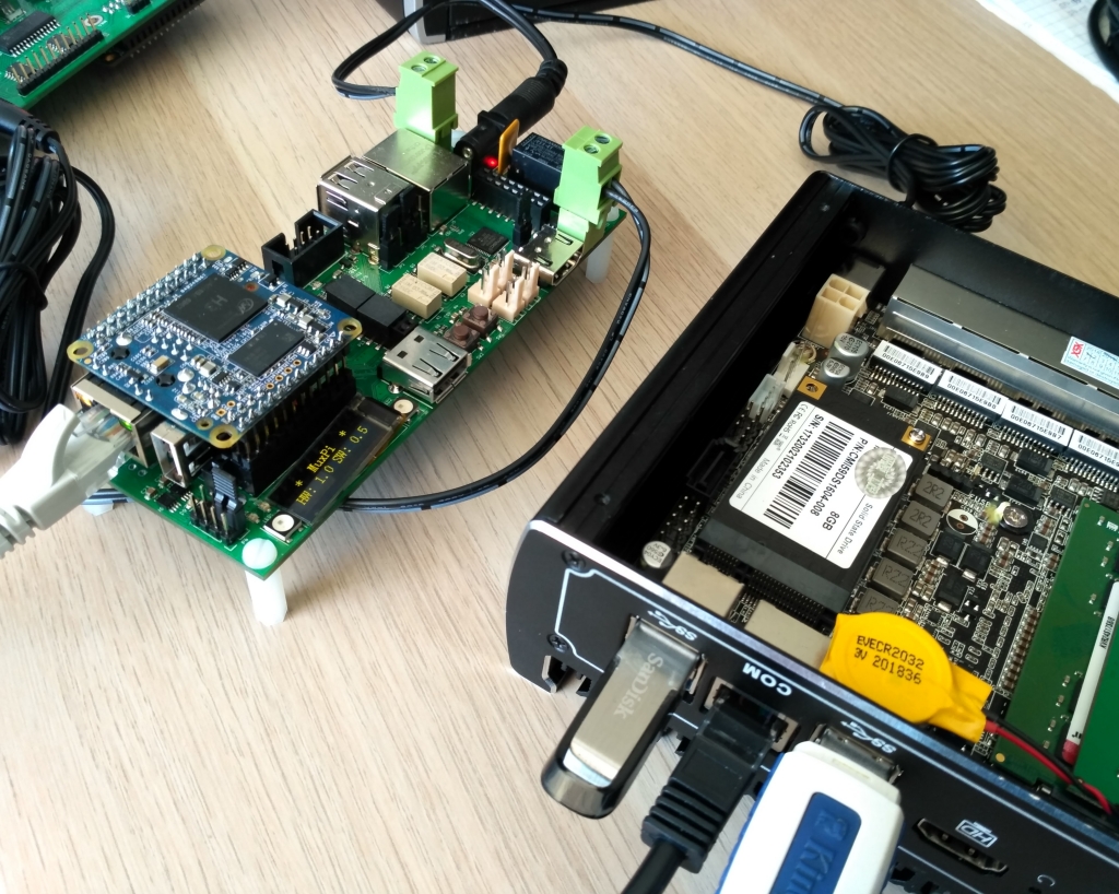
Providing a DUT connection to a remote location over Ethernet
Connectivity with the MuxPi can be achieved through:
- serial connection debug UART0 (addon header)
- serial connection debug UART0 (micro USB connector)
- network connection (Ethernet port from NanoPi NEO board)
From the moment of a successful connection with NanoPi, opens up multiple options for setting communication between muxPi and Device Under Test:
- Ethernet (onboard USB-ETH converter)
- USB OTG (NanoPi built-in port)
- USB Host (up to 3 onboard USB host connectors)
- Serial interface (UART header with an adjustable voltage level)
Remote control over power supply for a DUT
Similar to RTE, muxPi controls the power of a DUT using an electromagnetic relay, with the difference of managing the state of the relay - MuxPi sets the power supply on/off by on-board STM32 microcontroller. Just connect the power supply to DUT through pluggable terminal blocks attached to muxPi power sockets.
Power control circuitry represents another additional option, which is measuring the current consumption of a Device Under Test. It evaluates the current draw using HAL effect current sensor which gives galvanic isolation from the control logic elements.
SD card multiplexing
One of the most anticipated muxPi’s feature is switching or flashing a microSD card without the need of ejecting the card itself. For this purpose, it is required to use special IDC <-> microSD adapter cable that is available in our shop.
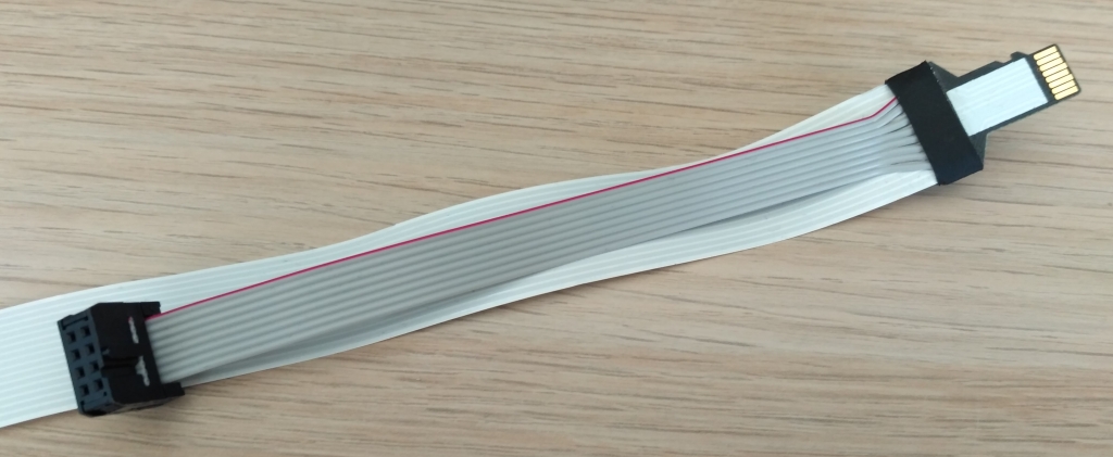
Switching card attached to muxPi’s SD card reader (part of USB HUB integrated circuit) is possible with SD-MUX - a multiplexer of microSD card which allows to connect the card either to SD-READER or a Device Under Test. Controlling system data of DUT or directly flashing the SD card never been easier - there is no need for manually ejecting and inserting the card back to the device anymore.
Flashing and controlling Samsung mobile devices
Thanks to derived USB-M header that has controllable by MuxPi Vbus and ID
pins, it is possible to handle connected mobile devices. This connector is an
endpoint of a larger entity which enables:
- ID switching (ID can be connected to ground through a potentiometer or left open),
- power switching on and off with
Vbusline (it is mandatory for entering e.g. “download mode”), - redirecting mobile’s USB data lines either to NanoPi’s USB or to MuxPi’s DUT UART.
Writing EDID to a DUT over HDMI connection
Extended Display Identification Data is a metadata format for display devices and in simple words, it describes the monitor’s capabilities that is connected through DVI or HDMI video cables (VGA uses it occasionally).
MuxPi is capable of injecting full EDID descriptor into DUT HDMI output through
full sized HDMI connector with connected only DDC channel wires, hot plugpin,
VCC and GND pins, all controllable by STM32 Cortex-M0 microcontroller.
DyPers
DyPer is an abbreviation for “Dynamic jumPer” and is a small, electromagnetic relay which is controllable by software. The muxPi board consists of 2 DyPers with 2 channels each, giving 4 operational switches that can act as regular jumpers or switches.
You can ask: “Why do I need them?”.
If a user has to test remotely the platform that requires pressing a button to power up the whole device, this is the answer to this problem. DyPer can switch signals up to 0.5A and both channels are separated galvanically, providing stable work without any unwanted environmental influences.
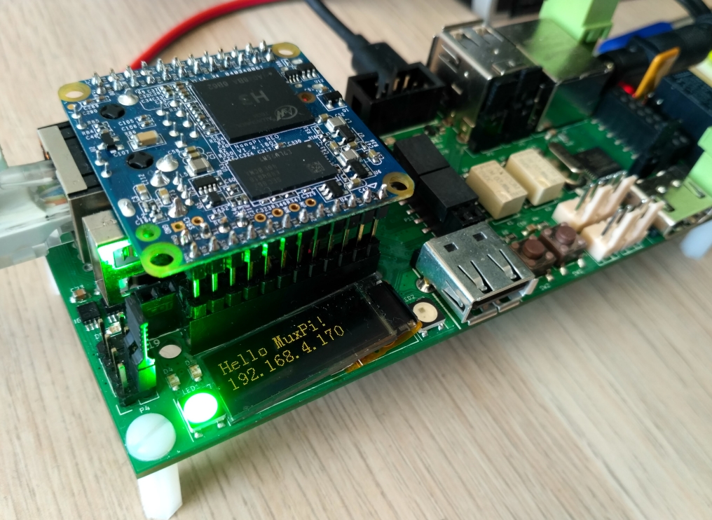
Additional user interface
MuxPi has many built-in, interactive user interface elements such as:
- monochrome LEDs indicating power presence, serial/network/SD card reader activity and two general purpose LEDs connected directly to NanoPi,
- two general purpose RGB LEDs,
- 128x32 yellow OLED display fully controllable via STM32 Cortex-M0.
The general purpose elements can be used in countless solutions. In 3mdeb’s lab, where we have board farm consists of many testing devices, the use-case for UI is an indicator which validation board has correct connection with DUT (set suitable color for RGB LED) and which IP address is set to each muxPi (OLED display).
The simplest example of a use-case
In the recording below I have demonstrated the basic usage of STM32 Cortex-M0 firmware for remote control over DUT’s power supply. The left pane shows output from NanoPi and STM32 Cortex-M0 communication, on the right we can see the output from DUT’s serial (booting platform log).
Additionally, I have shown full help page from STM32 stock firmware already flashed on the MuxPi board, presenting the whole set of microcontroller capabilities.

The short explanation of commands shown in the recording:
gpio mode 3 out- sets NanoPi gpio responsible for powering up Cortex-M0 to output mode,gpio write 3 1- powers up the microcontroller,screen /dev/ttyS2 115200,cs8,ixon,ixoff- opens serial connection with UART2, which is a channel for communication between NanoPi and the STM32 unit.
Summary
Are you trying to flash your mobile phone or test DUT’s video with various graphics settings? Or maybe you are a firmware/software developer with the desire to work remotely on various platforms? MuxPi validation board ensures that all the above problems are no longer scary - simply check our product site or order the board now at shop.3mdeb.com!
If you think we can help in improving the security of your firmware or you
looking for someone who can boost your product by leveraging advanced features
of used hardware platform, feel free to
book a call with us or
drop us email to contact<at>3mdeb<dot>com. If you are interested in similar
content feel free to sign up for our newsletter.